
Explosion-proof locking mechanism for temperature sensor element

A technology of temperature sensor and locking mechanism, which is applied to the parts of thermometers, thermometers, and thermometers with electric/magnetic elements that are directly sensitive to heat. Problems such as expansion and contraction, increased maintenance and replacement costs, etc., achieve the effect of simple structure, convenient and reliable use, and improved service life

Inactive Publication Date: 2020-06-23
ZHEJIANG ZHENENG ELECTRIC POWER
View PDF7 Cites 0 Cited by
  • Summary
  • Abstract
  • Description
  • Claims
  • Application Information

AI Technical Summary

Problems solved by technology

[0003] In the actual production process, when the armored temperature element measures high-temperature components, the insulating filler inside the armored temperature element will be heated and expanded, and the use of traditional ferrules to fix the armored temperature element will cause the armored temperature element to fail to expand and contract , when the expansion is large, the insulating filler inside the armored temperature element will break through the stainless steel protective tube, and the armored temperature element will burst
This type of situation leads to a very high rate of damage to the armored temperature element, which not only affects the normal monitoring of the temperature signal of the thermal system, but also greatly increases the cost of maintenance and replacement

Method used


Image

  • Explosion-proof locking mechanism for temperature sensor element
  • Explosion-proof locking mechanism for temperature sensor element

Examples


Embodiment 1

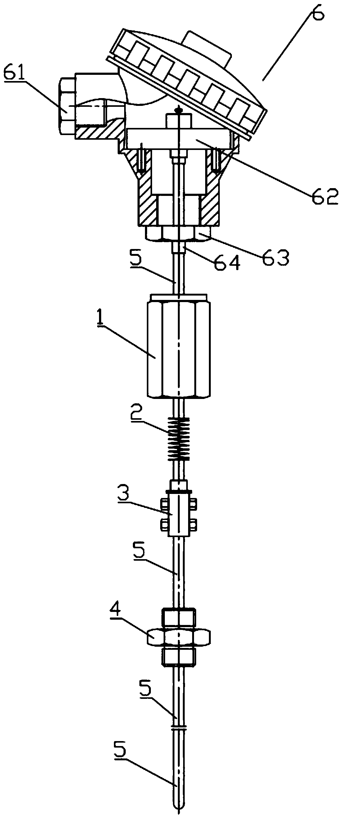
[0031] Such as Figure 1 to 2 As shown, an explosion-proof locking mechanism for a temperature sensor element includes a threaded sleeve 1, a telescopic spring 2, a locking sleeve 3, and a threaded joint 4; when in use, the armored temperature element 5 is inserted through from top to bottom. The threaded sleeve 1, the telescopic spring 2, the locking sleeve 3 and the threaded joint 4, and pass through; the threaded sleeve 1 has a cavity in it, and one end in the axial direction is provided with internal threads for connecting with One end of the threaded joint 4 is connected, and the other end has a baffle 11; the telescopic spring 2 is arranged between the threaded sleeve 1 and the locking sleeve 3, and after installation, it is accommodated in the threaded sleeve 1 In the cavity of, one end is in contact with the baffle 11 and the other end is in contact with the locking sleeve 3; the locking sleeve 3 is provided with at least one threaded hole in the radial direction, and t...

Embodiment 2

[0033] Such as Figure 1 to 2 As shown, an explosion-proof locking mechanism for a temperature sensor element includes a threaded sleeve 1, a telescopic spring 2, a locking sleeve 3, and a threaded joint 4;

[0034] When in use, the armored temperature element 5 is inserted into the threaded sleeve 1, the telescopic spring 2, the locking sleeve 3 and the threaded joint 4 from top to bottom, and passes out;

[0035] The threaded sleeve 1 has a cavity, and one end in the axial direction is provided with an internal thread for connecting with one end of the threaded joint 4, and the other end has a baffle 11;

[0036] The telescopic spring 2 is arranged between the threaded sleeve 1 and the locking sleeve 3, and after installation, it is accommodated in the cavity of the threaded sleeve 1, one end is in contact with the baffle 11, and the other end Contact with the locking sleeve 3;

[0037] The locking sleeve 3 is provided with at least one threaded hole in the radial direction, and th...


PUM


Abstract

The invention discloses an explosion-proof locking mechanism for a temperature sensor element. The explosion-proof locking mechanism comprises a threaded sleeve, a telescopic spring, a locking sleeveand a threaded joint. A cavity is formed in the threaded sleeve, internal threads are arranged at one end of the threaded sleeve in the axial direction, and a baffle is arranged at the other end of the threaded sleeve. The telescopic spring is arranged between the threaded sleeve and the locking sleeve. At least one threaded hole is formed in the locking sleeve in the radial direction. The two ends of the screwed joint in the axial direction are provided with external threads, one end of the screwed joint is used for being connected with the threaded sleeve, and the other end of the screwed joint is used for being connected with a component with measured temperature. The explosion-proof locking mechanism for the temperature sensor element is a novel tool. In the actual use process, the failure rate of the armored temperature element is obviously reduced, the service life of the armored temperature element is prolonged, and meanwhile the explosion-proof locking mechanism is simple in structure, convenient to manufacture, easy to install, high in practicability and high in popularization value.

Description

Technical field [0001] The invention relates to the technical field of armored temperature elements, in particular to an explosion-proof locking mechanism for temperature sensor elements. Background technique [0002] For large-scale thermal power plants, armored thermocouples and thermal resistances are used as conventional temperature measurement elements and are widely used in major thermal systems. The advantages are high temperature resistance, fast thermal response time, and durability. The installation of the armored temperature element generally adopts a threaded joint and a ferrule joint. The threaded joint is used to connect the measured object, pipe, cylinder and other parts. The ferrule joint connects the armored temperature element and the threaded joint tightly to make the armor The temperature component is fixed on the component under test. The ferrule joint is generally composed of ferrule, seamless steel pipe and nut. After the nut is tightened, the ferrule is a...

Claims


Application Information

Patent Timeline
IPC IPC(8): G01K1/14G01K1/12G01K7/02
CPCG01K1/14G01K1/12G01K7/02
Inventor 袁岑颉沈路明陈丽丽马宁王煜晖
Owner ZHEJIANG ZHENENG ELECTRIC POWER
Learn More