
Lateral punching device and method of supporting plate

A technology of punching device and support plate, which is applied in the field of punching, can solve the problems of inaccurate punching position and deformation of the support plate of power distribution switchgear, and achieve the effect of improving the accuracy of punching and avoiding bending under force

Inactive Publication Date: 2020-06-23
何东海
View PDF0 Cites 0 Cited by
  • Summary
  • Abstract
  • Description
  • Claims
  • Application Information

AI Technical Summary

Problems solved by technology

[0004] The purpose of the present invention is to aim at the fact that in the prior art, punching holes on the side of the support plate of the power distribution switch cabinet is easy to deform the support plate of the power distribution switch cabinet, the position of the side punching of the support plate of the power distribution switch cabinet is not accurate, and the support plate of the power distribution switch cabinet There is a certain distance between the conveying and processing stations, and it needs to be transported again. A side punching device for the support plate of the power distribution switch cabinet is proposed with precise side punching without deformation and high side punching efficiency.

Method used


Image

  • Lateral punching device and method of supporting plate
  • Lateral punching device and method of supporting plate
  • Lateral punching device and method of supporting plate

Examples


Embodiment Construction

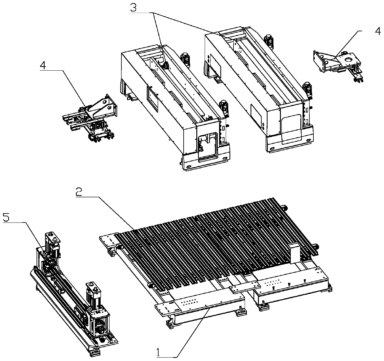
[0027] Such as figure 1 As shown, a support plate punching machine includes a frame 1, a conveying device 2, a side punching device 3, a handling device 4 and a bottom punching device 5; the conveying device 2 is arranged on the frame 1, Described side punching device 3 is provided with two groups, and side punching device 3 is installed on the frame 1, and side punching device 3 is positioned at the top of conveying device 2; Described carrying device 4 is arranged on the side On the side of the punching device 3, the bottom punching device 5 is connected to the discharge end of the conveying device 2; the side of the bottom punching device 5 is also provided with a discharge device, and the feeding device 2 The end is provided with a feeding device. The support plate is the support plate of the distribution switchgear,

[0028] The conveying device 2 is used to transport the movement of the support plate of the power distribution switch cabinet, the described side punching...


PUM


Abstract

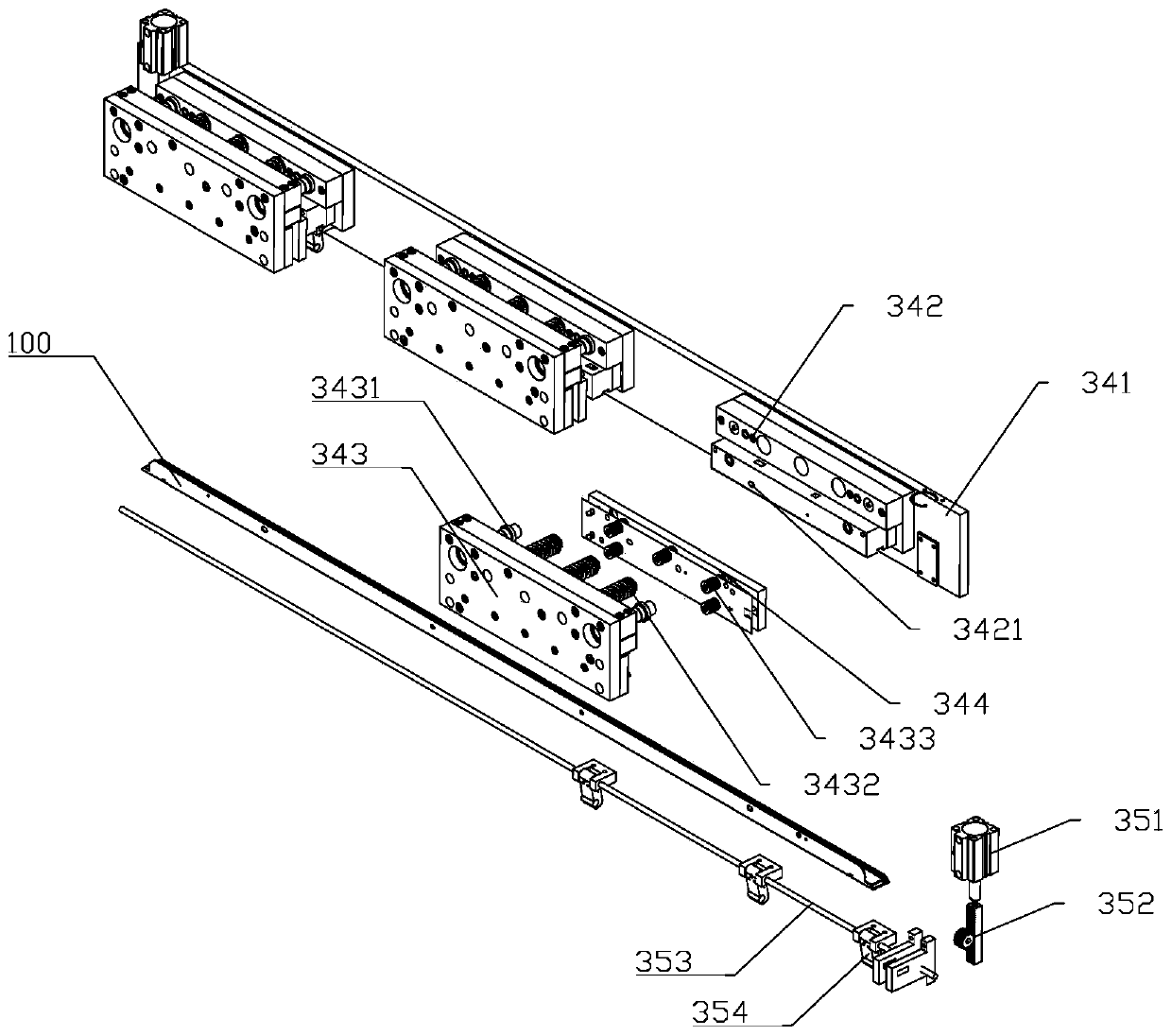
The invention relates to the technical field of punching, in particular to a lateral punching device of a supporting plate. The device comprises a mounting base, a transmission plate, a driving assembly, a punching mold, a limiting assembly, end positioning assemblies and a lifting assembly. The mounting base is mounted on a rack, the transmission plate is in moving connection to the mounting base, the driving assembly is mounted on the mounting base, the moving end of the driving assembly is connected with the telescopic end of the transmission plate, the punching mold is mounted on the mounting base, the limiting assembly is mounted on the punching mold, the end positioning assembly is mounted on the rack, the end positioning assemblies are located on the two sides of the punching mold,and the lifting assembly is located below the punching mold. The device has the advantages that side punching is precise and free of deforming, and side punching efficiency is high.

Description

technical field [0001] The invention relates to the technical field of punching, in particular to a side punching device for a support plate of a power distribution switch cabinet. Background technique [0002] The support plate of the power distribution switch cabinet is the main accessory in the power distribution switch cabinet. It is installed in the box of the power distribution switch cabinet. There are mounting holes in multiple directions and angles on the support plate, which are used to install other distribution devices Electric accessories. The punching operation of the support plate of the existing power distribution switch cabinet is to use a drilling machine, and the drill bit drills with the movement of the support plate of the power distribution switch cabinet, and then returns to the starting position to continue operation. The position of the hole drilled by this type of drilling device is prone to deviation, and the accuracy is not high. This method is ...

Claims


Application Information

Patent Timeline
Patent Type & Authority Applications(China)
IPC IPC(8): B21D28/34B21D28/26B21D43/00
CPCB21D28/26B21D28/34B21D43/003
Inventor 何东海邰照坡耿书琴
Owner 何东海
Learn More