Riveting tooling for sub-beam of heliostat

A technology for riveting tooling and heliostats, which is applied in installation, instruments, lighting and heating equipment, etc., can solve the problems of easy assembly errors, labor and time, and achieve the effects of reducing labor intensity, saving materials, and reducing weight

Active Publication Date: 2021-12-21
ZHEJIANG SUPCON SOLAR TECHNOLOGY CO LTD
View PDF9 Cites 0 Cited by
  • Summary
  • Abstract
  • Description
  • Claims
  • Application Information

AI Technical Summary

Problems solved by technology

[0003] The heliostat frame has a large number of parts in the assembly process, and the assembly process is labor-intensive and time-consuming, especially the assembly of the sub-beam assembly. The sub-beam assembly includes two support beams with different lengths but the same structure. Beams are positioned differently during assembly and are prone to assembly errors

Method used


Image

  • Riveting tooling for sub-beam of heliostat
  • Riveting tooling for sub-beam of heliostat
  • Riveting tooling for sub-beam of heliostat

Examples


Embodiment Construction

[0037] A sub-beam riveting tool for heliostats proposed by the present invention will be further described in detail below in conjunction with the accompanying drawings and specific embodiments. Advantages and features of the present invention will be apparent from the following description and claims.

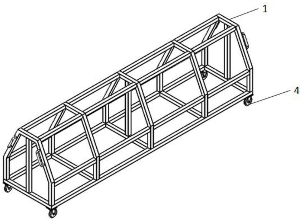
[0038] see Figure 1 to Figure 8 As shown, the present invention provides a sub-beam riveting tooling for a heliostat, including a base 1 and at least one set of sub-beam riveting units 2, see image 3 As shown, the subframe riveting unit 2 includes a first support member 21 , two second support members 22 and several third support members 23 .

[0039] The base 1 is used to install the subframe riveting unit 2, such as figure 2 As shown, in this embodiment, the base 1 adopts a truss structure, which includes a lower chassis and an upper support structure. The side waist surfaces of the waist platform are evenly arranged in a stepped form from top to bottom, which can comp...


PUM


Abstract

The invention discloses a sub-beam riveting tool for a heliostat, which includes a base and at least one set of sub-beam riveting units, wherein the sub-beam riveting unit includes a first support piece, two second support pieces and several first support pieces. Three supporting parts, wherein the first supporting part includes a first connecting plate and a first supporting plate, and the riveting surface of the first supporting plate is provided with a beam positioning structure, and the sub-beam components are sequentially installed on the sub-beam riveting according to their assembly structure unit, and then rivet the riveting holes in turn. By providing a sub-beam riveting tool, the rapid riveting of the sub-beam assembly can be realized, and the labor intensity of the workers can also be reduced. At the same time, the girder positioning structure can be used for different girders. Positioning, preventing misassembly of support beams, and realizing accurate riveting of sub-frame components.

Description

technical field [0001] The invention belongs to the field of solar thermal power generation, in particular to a riveting tool for a sub-beam of a heliostat. Background technique [0002] The function of the heliostat in the tower solar thermal power generation is to gather sunlight to the heat sink, and the flatness of the mirror surface of the heliostat will affect the reflection accuracy of the mirror surface, which in turn will affect the incident energy of the heat sink. Therefore, It is necessary to control the shape of the mirror surface of the heliostat, and then improve the light-gathering ability of the heliostat. In order to control the mirror surface shape of the heliostat, there are specific requirements for the position degree and relative position relationship distribution of the connectors on the mirror bracket. [0003] The heliostat frame has a large number of parts in the assembly process, and the assembly process is labor-intensive and time-consuming, esp...

Claims


Application Information

Patent Timeline
Patent Type & Authority Patents(China)
IPC IPC(8): G02B7/183F24S23/70
CPCG02B7/183F24S23/70Y02E10/40
Inventor 江远财樊峰蒋晓谢汉杰周静谢继谦
Owner ZHEJIANG SUPCON SOLAR TECHNOLOGY CO LTD
Why Eureka
Try Eureka