Rail bottom side flaw detection undercarriage for welded joint weld joint of welded rail base steel rail
A technology for welding joints and landing gear, which is applied in the direction of material analysis, measuring devices and instruments using sonic/ultrasonic/infrasonic waves, which can solve the problems of inability to improve the welding process, stress concentration, and reduce the effective cross-section of the rail to improve efficiency. And the accuracy of flaw detection, the effect of automatic control
- Summary
- Abstract
- Description
- Claims
- Application Information
AI Technical Summary
Problems solved by technology
Method used
Image

Examples
Embodiment 1
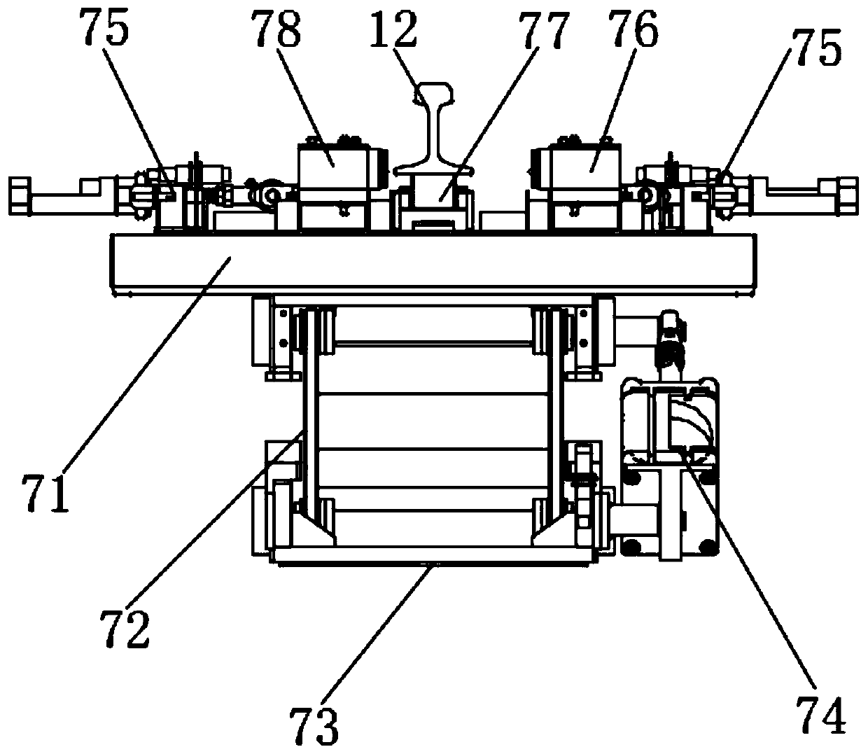
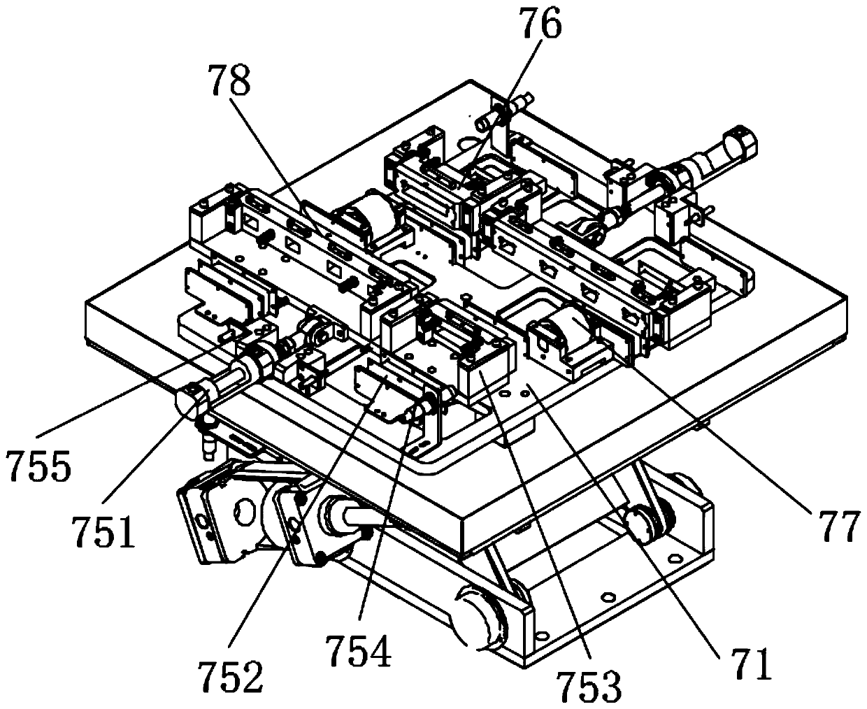
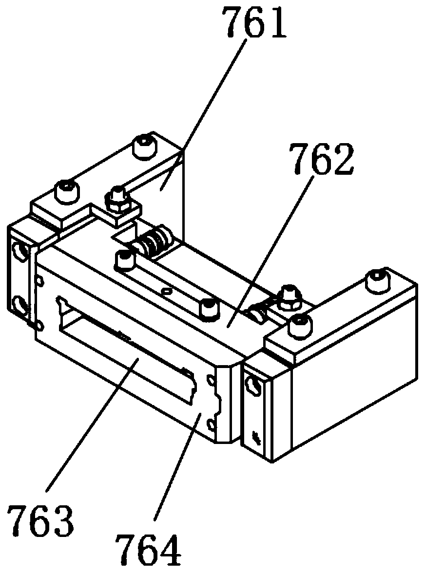
[0035] like figure 1 As shown, in this embodiment, a rail bottom side flaw detection landing gear for the welded rail base rail welding joint weld seam includes a rail bottom flaw detection base 71 located below the rail 12, two A on the rail bottom flaw detection base 71 The transmitting structure 76 and two A receiving structures 78 arranged on the rail bottom flaw detection base 71, the A transmitting structure 76 corresponds to the A receiving structure 78 and is respectively arranged on both sides of the rail 12;
[0036] The A transmitting structure 76 includes the A transmitting probe that sends the A ultrasonic wave inclined to the length direction of the rail 12, and the A receiving structure 78 includes several A receiving probes that receive the A ultrasonic wave, and the A receiving probe receives the A ultrasonic wave in a vertical direction. In the emission direction of A ultrasonic wave;
[0037] The directions in which the two A transmitting probes emit ultras...
Embodiment 2
[0045]On the basis of the above-mentioned embodiments, in this embodiment, the rail bottom flaw detection base 71 is provided with two rail bottom flaw detection structure drive devices that can respectively drive the A transmitting structure 76 and the A receiving structure 78 away from or close to the rail 12 75. Utilizing the driving device 75 of the rail bottom flaw detection structure, the distance between the A transmitting structure 76 or the A receiving structure 78 and the rail 12 can be adjusted. When the rail 12 is placed, the A transmitting structure 76 and the A receiving structure 78 are controlled to be far away from the rail 12, which is convenient for installation 1. Place the steel rail 12 to avoid structural damage caused by collision. After the rail is placed, the A transmitting structure 76 or the A receiving structure is moved inwards and close to the rail 12 to reduce external interference and avoid affecting the detection accuracy.
[0046] like figu...
Embodiment 3
[0069] like figure 1 , Figure 5 As shown, on the basis of the above embodiments, in this embodiment, a flaw detection base lifting mechanism 72 is provided under the rail bottom flaw detection base 71, and a flaw detection base mounting seat 73 is disposed under the flaw detection base lifting mechanism 72, The flaw detection base lifting mechanism 72 is transmission-connected with a flaw detection base drive structure 74 . The flaw detection base driving structure 74 is used to drive the flaw detection base lifting mechanism 72, which can drive the rail bottom flaw detection base 71 to move in the vertical direction to facilitate the control of the rail bottom flaw detection base 71 lifting, so that after the rail 12 that needs flaw detection is installed, the rail bottom flaw detection The base 71 is moved into place, so as to prevent the transmission and positioning of the rail 12 from being affected by the rail bottom flaw detection base 71 and the structure above it.
...
PUM
 Abstract
Description
Claims
Application Information
 - R&D
- Intellectual Property
- Life Sciences
- Materials
- Tech Scout
- Unparalleled Data Quality
- Higher Quality Content
- 60% Fewer Hallucinations
Browse by: Latest US Patents, China's latest patents, Technical Efficacy Thesaurus, Application Domain, Technology Topic, Popular Technical Reports.
© 2025 PatSnap. All rights reserved.Legal|Privacy policy|Modern Slavery Act Transparency Statement|Sitemap|About US| Contact US: help@patsnap.com