
Three-dimensional laser scanning instrument for ancient building modeling

A 3D laser and model building technology, applied in the field of 3D scanning, can solve the problems of scanner vibration, troublesome adjustment, and affecting the scanning accuracy of the scanner, and achieve the effect of reducing vibration and reducing vibration

Active Publication Date: 2020-06-19
CHUZHOU VOCATIONAL & TECHN COLLEGE
View PDF10 Cites 8 Cited by
  • Summary
  • Abstract
  • Description
  • Claims
  • Application Information

AI Technical Summary

Problems solved by technology

[0004] Existing 3D laser scanners are usually supported by a tripod stand when in use, and the three legs of the tripod stand need to be adjusted separately when adjusting the height, which is troublesome to adjust, and most of the existing 3D laser scanners are in use. The fixed structure makes it impossible to scan the entire ancient building. At the same time, due to the complex terrain, the mobile scanner will vibrate during the movement, which will affect the scanning accuracy of the scanner.

Method used


Image

  • Three-dimensional laser scanning instrument for ancient building modeling
  • Three-dimensional laser scanning instrument for ancient building modeling
  • Three-dimensional laser scanning instrument for ancient building modeling

Examples


Embodiment Construction

[0027] The following will clearly and completely describe the technical solutions in the embodiments of the present invention with reference to the accompanying drawings in the embodiments of the present invention. Obviously, the described embodiments are only some, not all, embodiments of the present invention. Based on the embodiments of the present invention, all other embodiments obtained by persons of ordinary skill in the art without making creative efforts belong to the protection scope of the present invention.

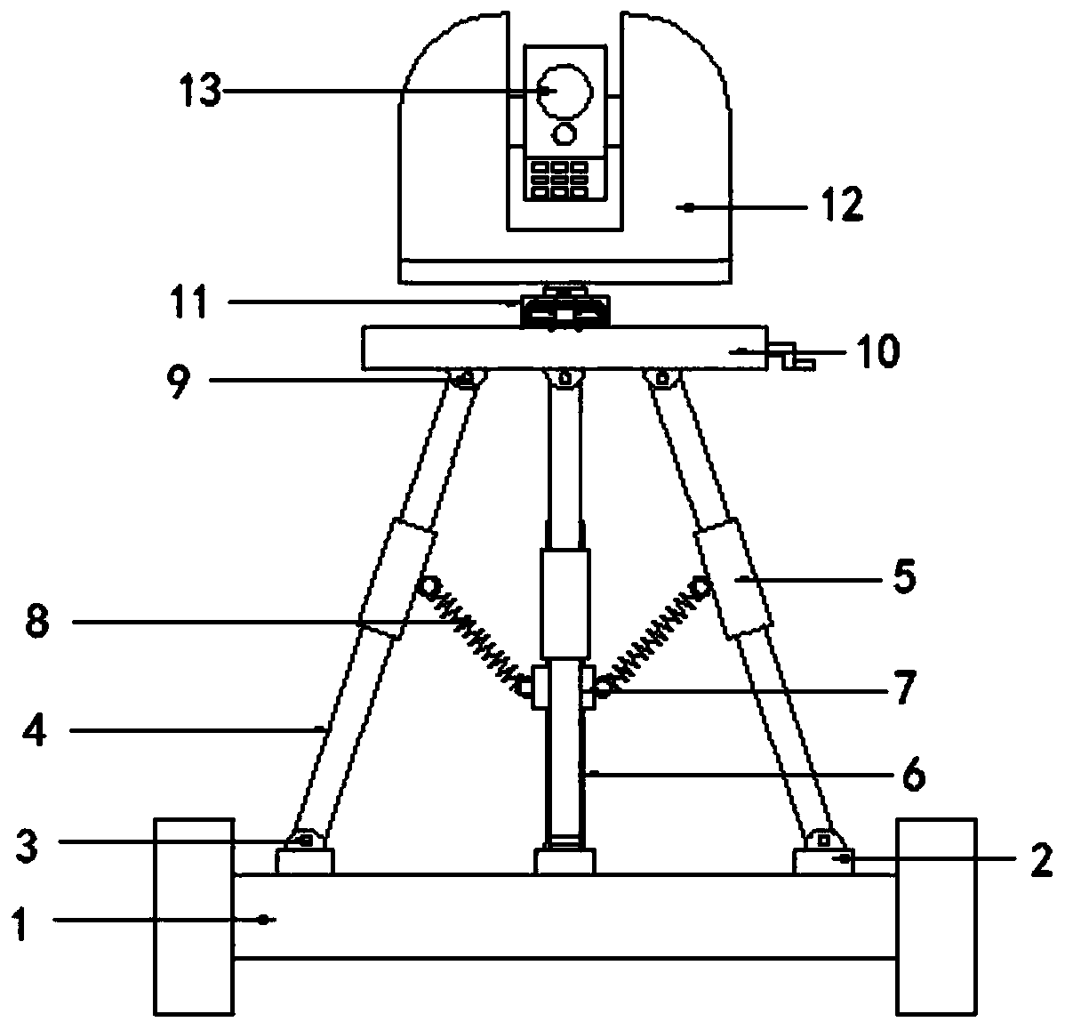
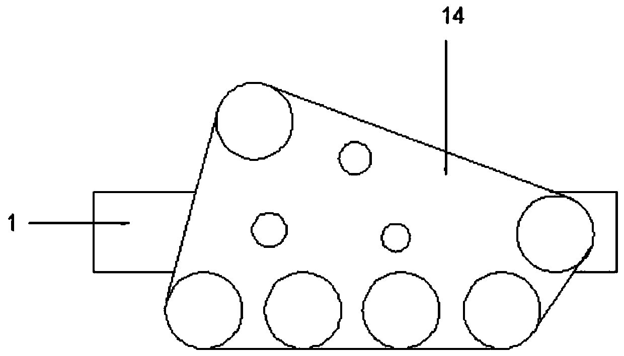
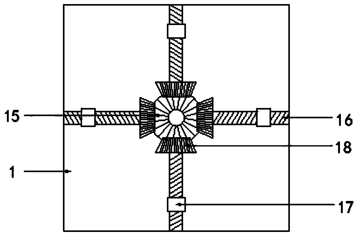
[0028] see Figure 1-7, the present invention provides a technical solution: a three-dimensional laser scanner for building models of ancient buildings, comprising: a base 1, a screw 16 is provided inside the base 1 and four sets of screws 16 are provided, and four sets of the screw 16 are distributed in the middle of the four sides of the base 1, the end of the screw 16 is connected with a first driven gear 18 and the middle of the base 1 is provided with a t...


PUM


Abstract

The invention discloses a three-dimensional laser scanning instrument for ancient building modeling. The three-dimensional laser scanning instrument for the ancient building modeling comprises a base;four groups of screw rods are arranged in the base; the four groups of the screw rods are distributed in the middle of the four sides of the base; the tail end of each screw rod is connected with a first driven gear, and a toothed disc is arranged in the centre of the base; the toothed disc is engaged with the first driven gear; and a sliding block is arranged on the surface of each screw rod. According to the three-dimensional laser scanning instrument for ancient building modeling, an adjusting rod is arranged in a mounting seat for matching a connecting rod to rotate, so that a second driven gear drives a driving gear to rotate to drive a rotating shaft to rotate; the rotating shaft is connected to the fixed seat so as to drive a fixed shaft to rotate transversely at 360 degrees; an electric pushing rod and a connecting shaft are arranged in the fixed seat; the electric pushing rod pushes the connecting shaft to be in contact with the three-dimensional laser scanning instrument soas to clamp and fix the three-dimensional laser scanning instrument; simultaneously, the motor drives the rotating shaft to rotate through a driving chain, so that the three-dimensional laser scanninginstrument can rotate longitudinally at 360 degrees; and wide-angle photographing of the three-dimensional laser scanning instrument can be realized by matching crawler-type wheels.

Description

technical field [0001] The invention relates to the technical field of three-dimensional scanning, and more specifically relates to a three-dimensional laser scanner for building models of ancient buildings. Background technique [0002] 3D laser scanning technology, also known as real scene replication technology, is a technological revolution in the field of surveying and mapping after GPS technology. It breaks through the traditional single-point measurement method and has the unique advantages of high efficiency and high precision. 3D laser scanning technology can provide 3D point cloud data of the scanned object surface, so it can be used to obtain high-precision and high-resolution digital terrain models. [0003] BIM (Building Information Modeling) technology was first proposed in 2002 and has been widely recognized by the industry around the world. It can help realize the integration of building information, from the design, construction, operation of the building t...

Claims


Application Information

Patent Timeline
IPC IPC(8): F16M11/24F16M11/06F16M11/10F16M11/18F16M11/04F16F15/04G01B11/24G01C11/00G01C11/02
CPCF16F15/04F16M11/04F16M11/06F16M11/10F16M11/18F16M11/24G01B11/24G01C11/00G01C11/02
Inventor 朱宝黄展华刘青高玉春张瑞
Owner CHUZHOU VOCATIONAL & TECHN COLLEGE
Learn More