
A hydraulic pump cavitation state detection system

A technology of cavitation state and detection system, which is applied in fluid pressure actuation system testing, fluid pressure actuation devices, mechanical equipment, etc., can solve problems such as reducing work efficiency, fatigue damage of pump internal parts, and inability to simulate real cavitation

Active Publication Date: 2022-04-08
TAIYUAN UNIV OF TECH
View PDF0 Cites 0 Cited by
  • Summary
  • Abstract
  • Description
  • Claims
  • Application Information

AI Technical Summary

Problems solved by technology

The cavitation of the hydraulic pump is the direct cause of cavitation in the pump, which aggravates the noise and impact of the hydraulic pump, reduces the working efficiency, and even causes the fatigue damage of the parts in the pump. Therefore, cavitation has become one of the main factors affecting the performance of the hydraulic pump.
Many scholars and researchers have studied the cavitation of hydraulic pumps, but they basically focus on the theory and simulation of cavitation mechanism, which cannot simulate real cavitation, and there are many factors that affect cavitation. Simulation and theory Studies do not adequately account for all influencing factors

Method used


Image

  • A hydraulic pump cavitation state detection system
  • A hydraulic pump cavitation state detection system
  • A hydraulic pump cavitation state detection system

Examples


Embodiment Construction

[0036] The following will clearly and completely describe the technical solutions in the embodiments of the present invention with reference to the accompanying drawings in the embodiments of the present invention. Obviously, the described embodiments are only some, not all, embodiments of the present invention. Based on the embodiments of the present invention, all other embodiments obtained by persons of ordinary skill in the art without making creative efforts belong to the protection scope of the present invention.

[0037] The purpose of the present invention is to provide a hydraulic pump cavitation state detection system, which can truly and comprehensively detect the cavitation state of the hydraulic pump.

[0038] In order to make the above objects, features and advantages of the present invention more comprehensible, the present invention will be further described in detail below in conjunction with the accompanying drawings and specific embodiments.

[0039] Example...


PUM


Abstract

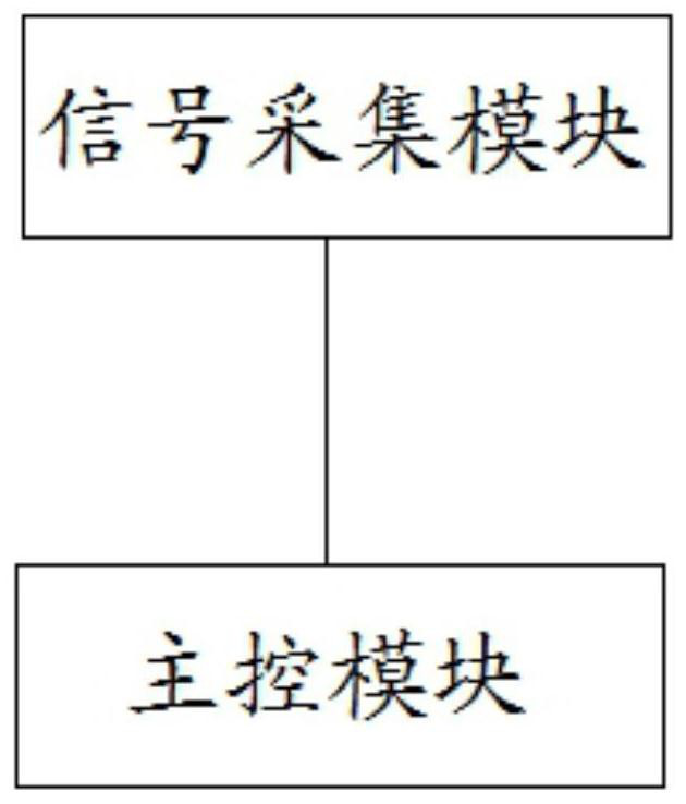
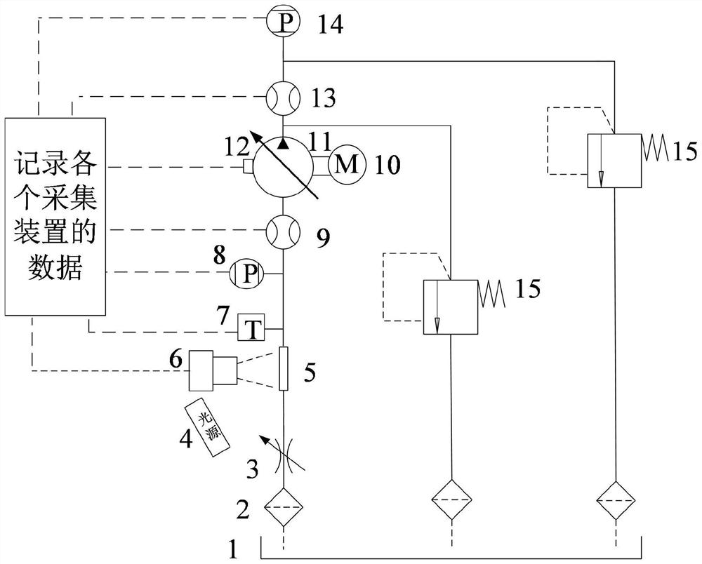
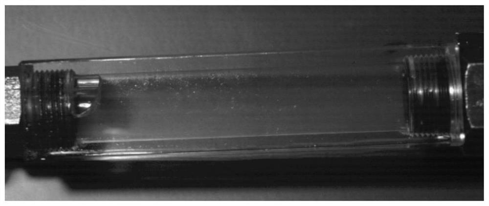
The invention relates to a hydraulic pump cavitation state detection system, which includes a signal acquisition module and a main control module; wherein, the signal acquisition module is used to collect the current operation data of the hydraulic pump to be tested in the hydraulic circuit; the current operation data includes the The temperature data of the oil inlet of the hydraulic pump to be tested, the pressure data of the oil inlet of the hydraulic pump to be tested, the flow data of the oil inlet of the hydraulic pump to be tested, the pressure data of the oil outlet of the hydraulic pump to be tested, the flow data of the oil outlet of the hydraulic pump to be tested and the data of the oil outlet of the hydraulic pump to be tested. Measure the vibration data of the pump casing of the hydraulic pump; the main control module integrates a well-trained extreme learning machine model; the trained extreme learning machine model is trained according to the historical operation data of the hydraulic pump and the cavitation state image of the hydraulic pump corresponding to the historical operation data owned. The invention determines the cavitation state of the hydraulic pump to be tested according to the current operation data of the hydraulic pump and the trained extreme learning machine model, and can truly and comprehensively detect the cavitation state of the hydraulic pump.

Description

technical field [0001] The invention relates to the technical field of hydraulic pump detection, in particular to a hydraulic pump cavitation state detection system. Background technique [0002] With the needs of industrial applications and social development, hydraulic pumps are developing in the direction of low noise, low flow pulsation, high speed and high pressure, and the impact of cavitation on the performance of hydraulic pumps has become more prominent. Cavitation phenomenon refers to the phenomenon that air or steam is separated from oil when its pressure drops below the air separation pressure or saturated vapor pressure somewhere in the process of liquid flow. Hydraulic oil usually contains some air suspended or dissolved in it. The amount of air in hydraulic oil is called air content, and the air content of hydraulic oil can reach 6-12% under standard atmospheric pressure. When the pressure is lower than the air separation pressure, the air will precipitate fr...

Claims


Application Information

Patent Timeline
Patent Type & Authority Patents(China)
IPC IPC(8): F15B19/00
CPCF15B19/007F15B19/005
Inventor 兰媛刘生政黄家海熊晓燕牛蔺楷钮晨光
Owner TAIYUAN UNIV OF TECH
Learn More