
Bearing pedestal machining system

A technology of processing system and bearing seat, which is applied in metal processing, metal processing equipment, metal processing machinery parts, etc., can solve problems such as inaccurate hole position, low operation efficiency, and impact on product quality

Active Publication Date: 2020-06-19
岳西县顺达机械有限公司
View PDF15 Cites 1 Cited by
  • Summary
  • Abstract
  • Description
  • Claims
  • Application Information

AI Technical Summary

Problems solved by technology

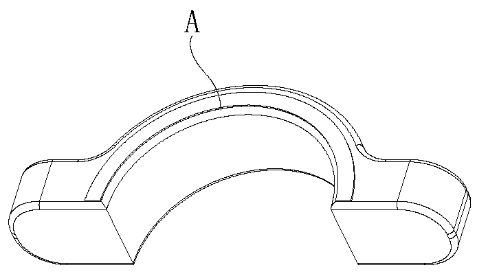
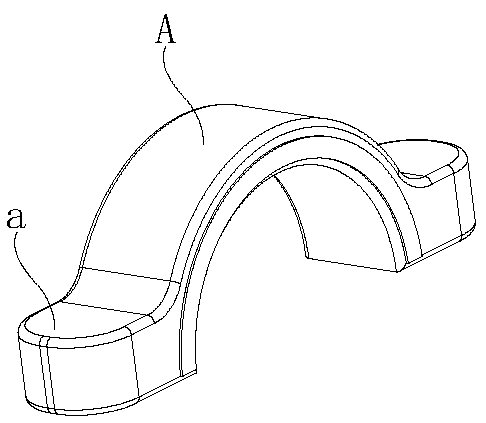
[0002] As a traditional bearing mounting part, the bearing seat is mostly cast in actual production. It is produced as a blank A through a casting mold. The blank A is mostly a semi-tubular structure. There are mounting surfaces a at both ends of the blank A. The mounting surfaces a are attached to each other, and mounting holes are drilled, the cores of the mounting holes are concentric, and fastening bolts are installed, so as to realize the clamping installation of the bearing. When processing the blank A, it is necessary to manually insert the blank Piece A is placed on the drilling machine, and the blank piece A is clamped by a clamp to realize the drilling operation on the mounting surface a at both ends of the blank piece A. The operation efficiency is low through manual hole rotation, and the blank piece A is often clamped. The inaccurate position of the hole caused by the inaccuracy will affect the quality of the final product

Method used


Image

  • Bearing pedestal machining system
  • Bearing pedestal machining system
  • Bearing pedestal machining system

Examples


Embodiment Construction

[0048] In order to make the objects and advantages of the present invention clearer, the present invention will be described in detail below in conjunction with the examples. It should be understood that the following words are only used to describe one or several specific implementation modes of the present invention, and do not strictly limit the protection scope of the specific claims of the present invention. As used herein, the terms "parallel" and "perpendicular" are not limited to their strict geometric definitions, but include reasonable and inconsistent tolerances for machining or human error;

[0049] Below in conjunction with accompanying drawing 1 to Figure 13 , the bearing housing processing system of the present invention is described in detail:

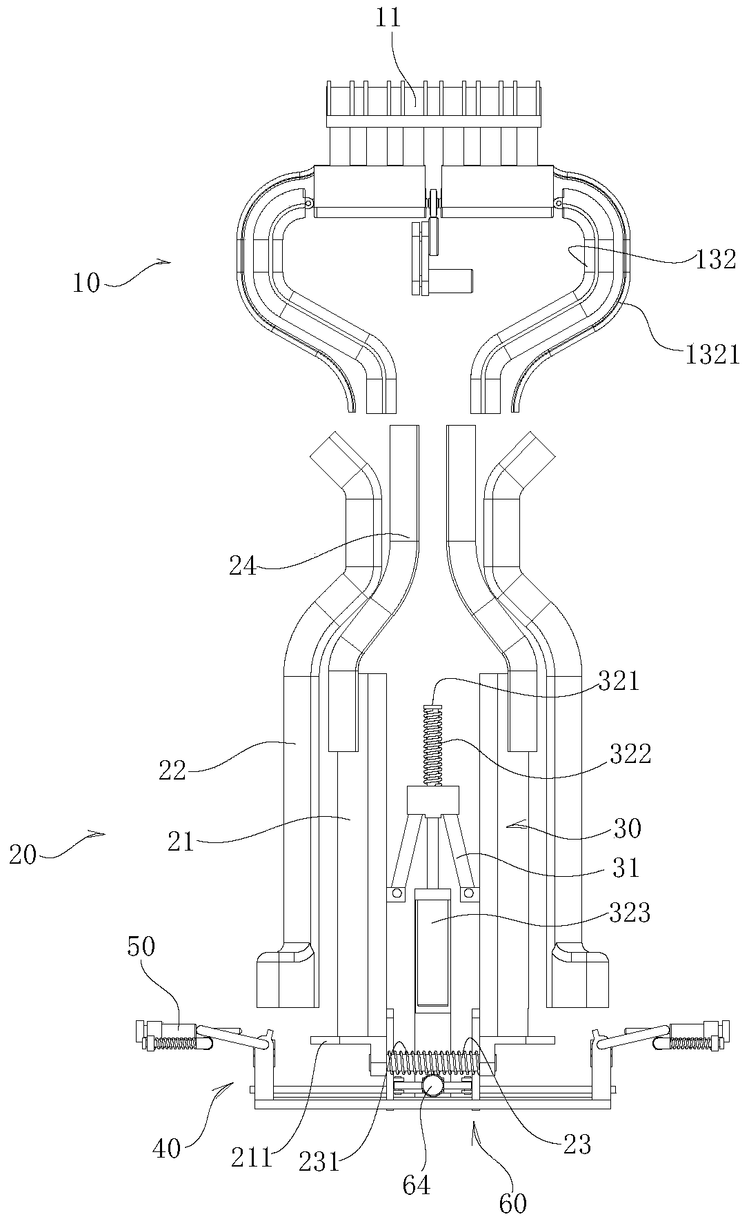
[0050] A bearing seat processing system, comprising a blank feeding mechanism 10, the outlet of the blank feeding mechanism 10 is connected to the inlet of a blank stacking mechanism 20, and the blank stacking mechani...


PUM


Abstract

The invention relates to a bearing pedestal machining system. The system comprises a bearing blank mechanism, an outlet of a blank feeding mechanism is connected with a feeding port of a blank stacking mechanism, the blank stacking mechanism is used for neatly stacking blanks, a core setting mechanism is arranged at the outlet of the blank stacking mechanism, and the core setting mechanism is usedfor core-setting the neatly stacked blanks; a clamping mechanism is arranged beside the outlet of the blank stacking mechanism and used for clamping installation faces at the two ends of a blank; a drill bit is arranged beside the clamping mechanism, and the drill bit moves in the vertical direction of the installation faces at the two ends of the blank and conducts drilling operation. The systemcan automatically realize the introduction of the blanks, thereby realizing automatic drilling operation on the bearing pedestal, and improving the production efficiency and quality of the bearing pedestal.

Description

technical field [0001] The invention relates to the field of bearing seat production, in particular to a bearing seat processing system. Background technique [0002] As a traditional bearing mounting part, the bearing seat is mostly cast in actual production. It is produced as a blank A through a casting mold. The blank A is mostly a semi-tubular structure. There are mounting surfaces a at both ends of the blank A. The mounting surfaces a are attached to each other, and mounting holes are drilled, the cores of the mounting holes are concentric, and fastening bolts are installed, so as to realize the clamping installation of the bearing. When processing the blank A, it is necessary to manually insert the blank Piece A is placed on the drilling machine, and the blank piece A is clamped by a clamp to realize the drilling operation on the mounting surface a at both ends of the blank piece A. The operation efficiency is low through manual hole rotation, and the blank piece A is ...

Claims


Application Information

Patent Timeline
IPC IPC(8): B23B41/00B23B47/00B23P15/00B23Q3/06B23Q7/00B65G57/03
CPCB23B41/00B23B47/00B23P15/003B23Q3/062B23Q7/00B65G57/03
Inventor 胡三六方继东
Owner 岳西县顺达机械有限公司
Learn More