
Optical sensing device and electronic apparatus

A sensing device and optical technology, which is applied in character and pattern recognition, instruments, printing image acquisition, etc., can solve the problems of large size, volume, and large space occupation, and achieve the effect of large luminous flux and good biometric detection effect

Pending Publication Date: 2020-06-16
SHENZHEN FUSHI TECH CO LTD
View PDF0 Cites 3 Cited by
  • Summary
  • Abstract
  • Description
  • Claims
  • Application Information

AI Technical Summary

Problems solved by technology

Due to the limited internal space of electronic equipment such as mobile phones, the imaging device that uses traditional lenses to achieve optical imaging has a large size and volume and takes up a lot of space.

Method used


Image

  • Optical sensing device and electronic apparatus
  • Optical sensing device and electronic apparatus
  • Optical sensing device and electronic apparatus

Examples


Embodiment Construction

[0029] In the specific description of the embodiments of the present application, it should be understood that when a substrate, sheet, layer or pattern is referred to as being "on" or "under" another substrate, another sheet, another layer or another pattern, it It may be "directly" or "indirectly" on another substrate, another sheet, another layer or another pattern, or one or more intervening layers may also be present. For the purpose of clarity, the thickness and size of each layer in the drawings of the specification may be exaggerated, omitted, or schematically represented. Also, the size of elements in the drawings does not utterly reflect an actual size.

[0030] The following will clearly and completely describe the technical solutions in the embodiments of the application with reference to the accompanying drawings in the embodiments of the application. Apparently, the described embodiments are only part of the embodiments of the application, not all of them. Based...


PUM

PropertyMeasurementUnit
thicknessaaaaaaaaaa

Abstract

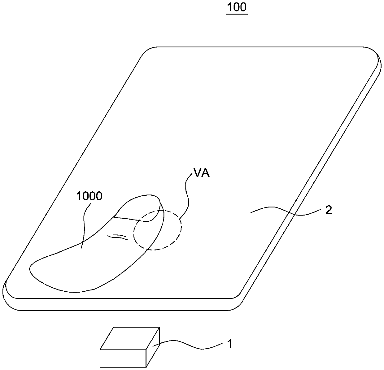
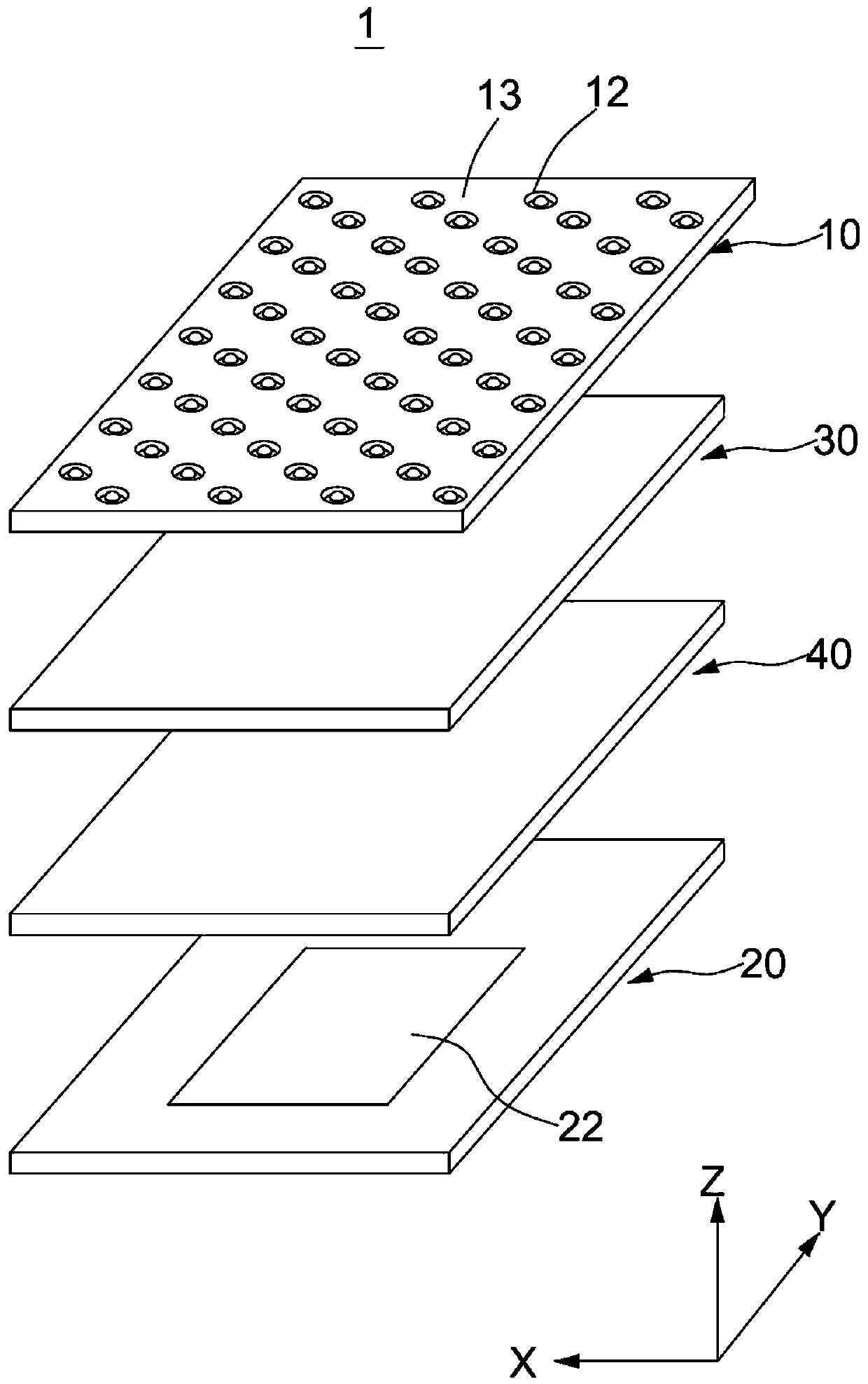
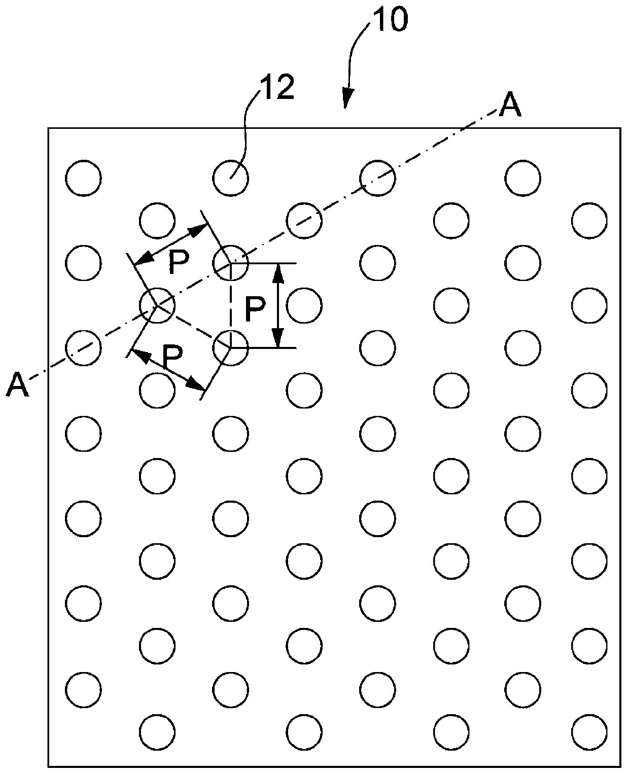
The invention discloses an optical sensing device comprising an image sensing chip which comprises a plurality of pixel units which are used for receiving light beams and converting the received lightbeams into corresponding electric signals; lens module, the image sensor is located above the image sensing chip. The lens module comprises a plurality of first lenses. The plurality of first lensesare arranged at intervals; the image sensing chip is provided with effective sensing areas respectively corresponding to the plurality of first lenses; wherein the effective sensing area comprises a plurality of pixel units, the first lens is used for converging a light beam to the corresponding effective sensing area, and the light beam of a target waveband can penetrate through the first lens toreach the corresponding effective sensing area and is converted into a corresponding electric signal; part or all of the first lenses are arranged in a triangular grid mode. The invention further discloses electronic equipment.

Description

technical field [0001] The present application relates to the field of optoelectronic technology, in particular to an ultra-thin optical sensing device and electronic equipment. Background technique [0002] With the advancement of technology and the improvement of people's living standards, users require more functions and stylish appearances for electronic devices such as mobile phones, tablet computers, and cameras. At present, the development trend of electronic devices such as mobile phones is to have a higher screen-to-body ratio and have functions such as fingerprint detection. In order to achieve a full-screen or near-full-screen effect and make electronic devices have a high screen-to-body ratio, the fingerprint detection technology under the screen has emerged as the times require. Due to the limited internal space of electronic devices such as mobile phones, imaging devices that use traditional lenses to achieve optical imaging take up a lot of space due to their...

Claims


Application Information

Patent Timeline
Patent Type & Authority Applications(China)
IPC IPC(8): G06K9/00
CPCG06V40/1324G06V40/1318
Inventor 林峰
Owner SHENZHEN FUSHI TECH CO LTD
Learn More