Tension test equipment and steel wire rope tension test method thereof

A tension test and steel wire rope technology, applied in the direction of applying stable tension/pressure to test the strength of materials, measuring devices, instruments, etc., can solve problems such as unstable clamping force, loose clamps and wire ropes, and failure to meet the needs of use. Achieve the effect of accurate tensile test results, improve accuracy, and improve stability

Active Publication Date: 2020-06-16
深圳天溯计量检测股份有限公司
View PDF11 Cites 4 Cited by
  • Summary
  • Abstract
  • Description
  • Claims
  • Application Information

AI Technical Summary

Problems solved by technology

[0003] The object of the present invention is to provide a kind of tension test equipment and the method for steel wire rope tension test thereof, to solve the problem that when the existing steel wire rope tension test equipment is carrying out the tension test, the steel wire rope is mainly clamped and fixed by the clamps of the tension test, so that When the steel wire rope is deformed by force, due to the unstable clamping force between the clamp and the steel wire rope, it is easy to cause loosening between the clamp and the steel wire rope, which will affect the result of the tensile test and cannot meet the technical problems of use.

Method used


Image

  • Tension test equipment and steel wire rope tension test method thereof
  • Tension test equipment and steel wire rope tension test method thereof
  • Tension test equipment and steel wire rope tension test method thereof

Examples


Embodiment Construction

[0030] The technical solutions of the present invention will be clearly and completely described below in conjunction with the embodiments. Apparently, the described embodiments are only some of the embodiments of the present invention, not all of them. Based on the embodiments of the present invention, all other embodiments obtained by persons of ordinary skill in the art without creative efforts fall within the protection scope of the present invention.

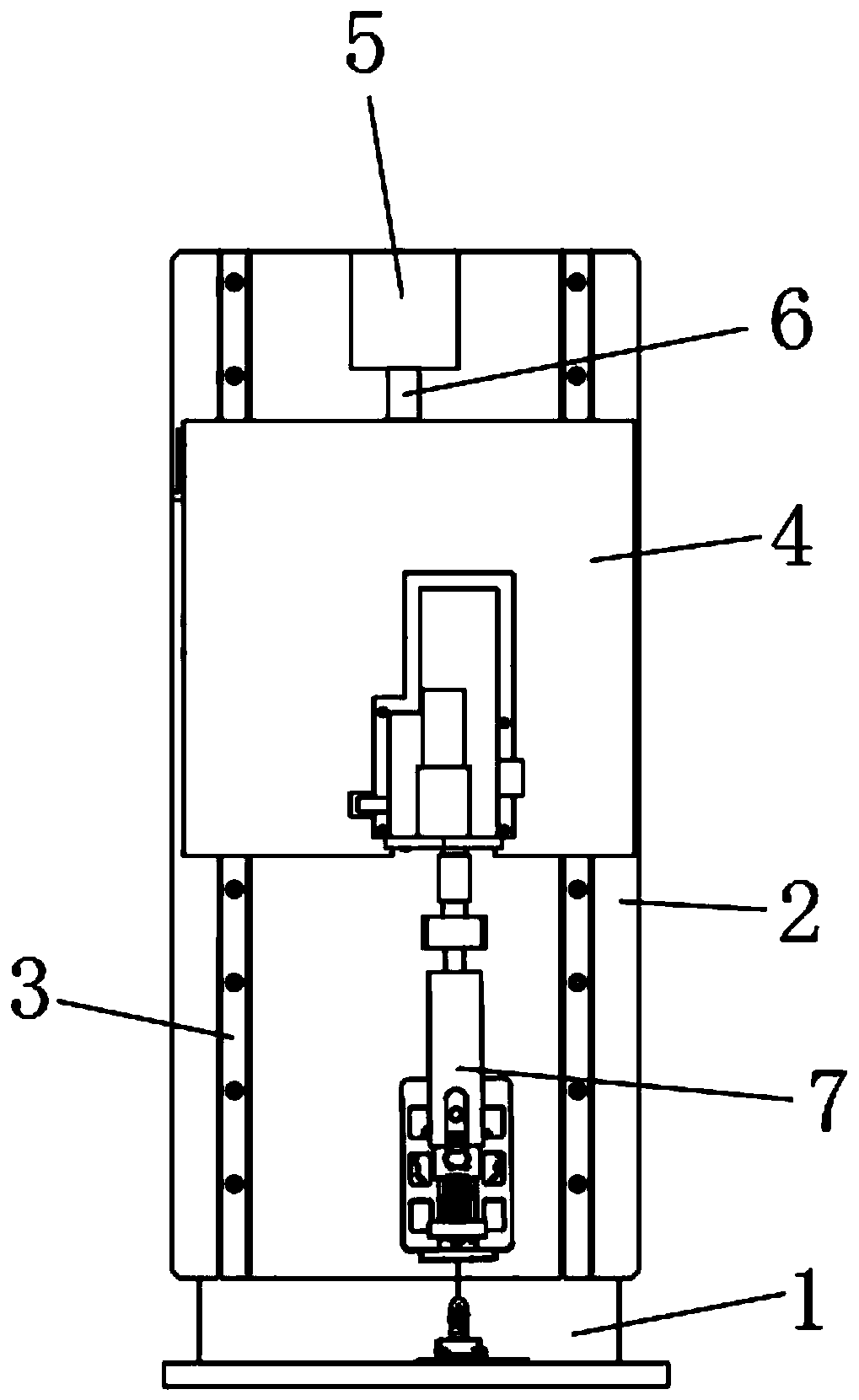
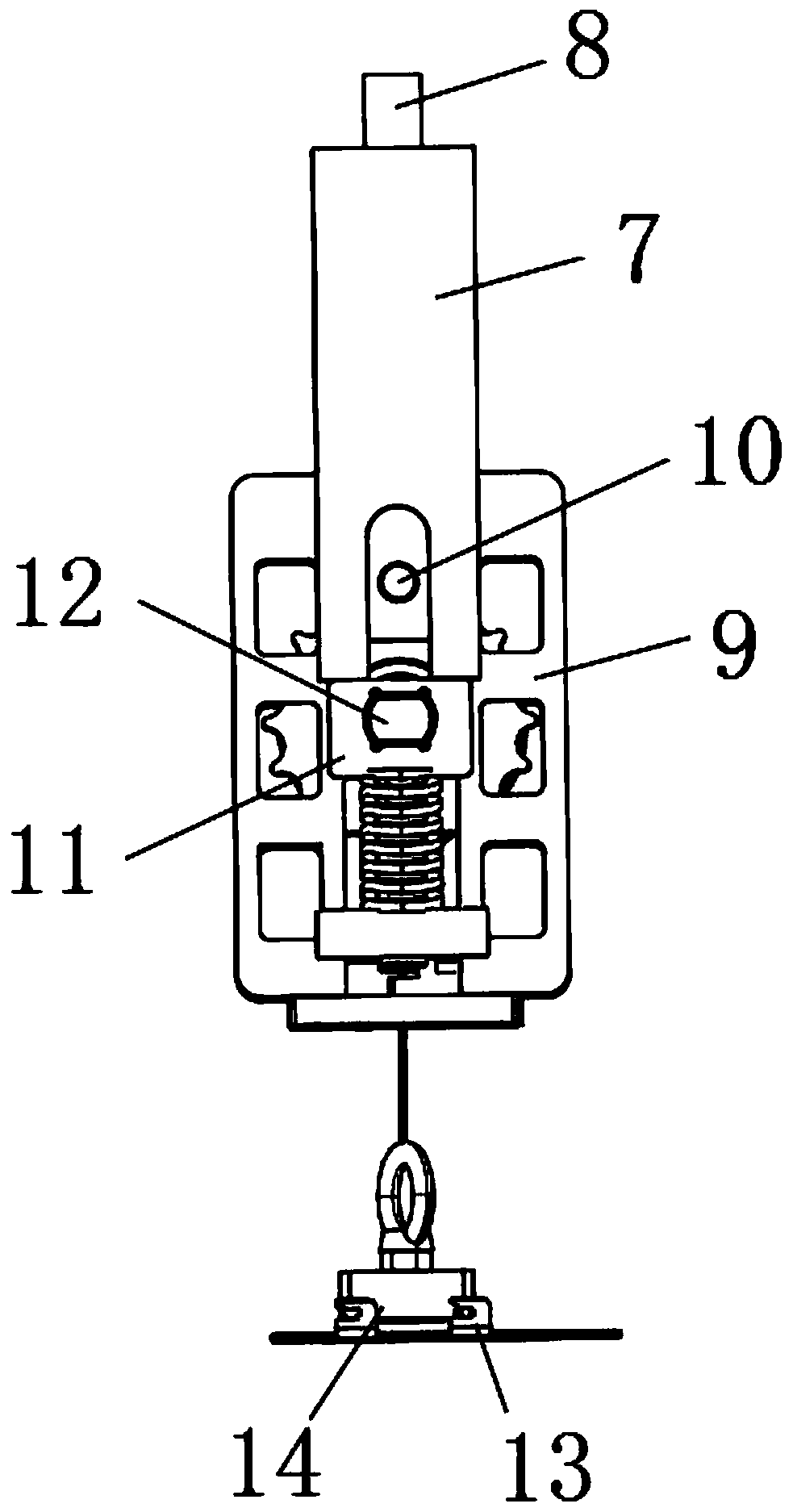
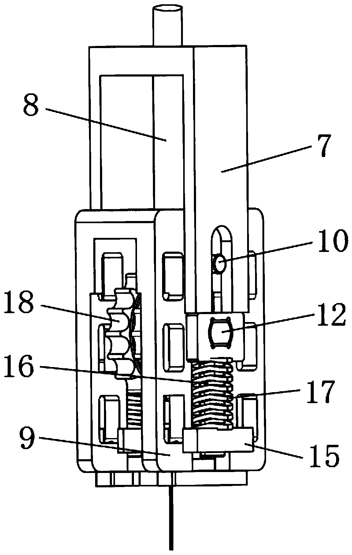
[0031] see Figure 1-6, a tensile test device, comprising: a card wheel 18 for clamping and fixing a steel wire rope, a connecting shaft 12 for fixing and supporting the card wheel 18, and a drive motor 5 for driving the first bracket 7 to move to drive the steel wire rope to stretch, The card wheel 18 is symmetrically arranged on one end of the connecting shaft 12, and the card wheel 18 is rotatably connected with the connecting shaft 12 through a key. 9 Fixed connection, the cross section of the connecting shaft 12 is a ...


PUM


Abstract

The invention discloses tension test equipment and a steel wire rope tension test method thereof. A tension bar is arranged, a clamping block is arranged at one end of the tension bar, and the clamping block and a clamping sleeve are clamped and fixed through a clamping groove; when a tension test is carried out, a transition block applies acting force to the clamping sleeve through a fixing shaft, the clamping sleeve applies acting force to the connecting rod through the connecting block, the acting force is transmitted to a first bracket through the connecting rod so as to provide drawing force for the steel wire rope; the clamping sleeve is clamped with the clamping block, the connection mode between the clamping sleeve and the clamping block is no longer hard contact, when the clampingsleeve transmits a tensile force, the steel wire rope is deformed under the action of tension, the instantaneous tensile force of the steel wire rope can be buffered in a clamping mode between the clamping sleeve and the clamping block, when the steel wire rope is stretched, the instantaneous acting force borne by the steel wire rope is not too large, and therefore damage to material performancecaused by the too large acting force at the moment of stress of the steel wire rope is avoided, and the tension test result of the steel wire rope is more accurate.

Description

technical field [0001] The invention relates to the field of test equipment, in particular to a tension test equipment and a method for performing a steel wire rope tension test, belonging to the technical field of tension test equipment applications. Background technique [0002] The tensile test of materials is mainly to determine the tensile properties of materials, and the quality of tensile properties can be detected by tensile tests. Tensile test (stress-strain test) generally clamps the two ends of the material sample on two fixtures at a certain distance, separates the two fixtures at a certain speed and stretches the sample, and measures the stress change on the sample. until the sample fails. Tensile test is one of the most widely used methods to study the mechanical strength of materials. When the existing steel wire rope tensile test equipment is used for tensile test, the steel wire rope is mainly clamped and fixed by the clamp of the tensile test, so that the ...

Claims


Application Information

Patent Timeline
Patent Type & Authority Applications(China)
IPC IPC(8): G01N3/08G01N3/02
CPCG01N3/02G01N3/08G01N2203/0003G01N2203/0017G01N2203/005G01N2203/028G01N2203/0682
Inventor 石霞曾宏勋黎丛兵龚天保龚敏吴百香
Owner 深圳天溯计量检测股份有限公司
Why Eureka
Try Eureka