
Independent hole carving system used for embroidery machine

An embroidery machine and hole carving technology, which is applied to the mechanism of embroidery machines, embroidery machines, and automatic control embroidery machines, etc. It can solve the problem of poor hole carving effect, inability to take into account both hole carving and multi-color embroidery, and lack of multi-color embroidery, etc. problems, to achieve the effect of large choice, flexible use, and improved applicability

Pending Publication Date: 2020-06-16
浙江镨美科智能刺绣设备有限公司
View PDF1 Cites 2 Cited by
  • Summary
  • Abstract
  • Description
  • Claims
  • Application Information

AI Technical Summary

Problems solved by technology

[0004] However, this independent engraved embroidery machine head has the following defects: Although the problem of poor engraving effect is solved by the independent drive of the engraved knife rod, the engraved hole rod and its drive are directly connected, so the engraved knife bar Only one needle bar can be configured for single-color embroidery, and it does not have the function of multi-color embroidery, that is, it cannot take into account both carving holes and multi-color embroidery

Method used


Image

  • Independent hole carving system used for embroidery machine
  • Independent hole carving system used for embroidery machine
  • Independent hole carving system used for embroidery machine

Examples


Embodiment example 1

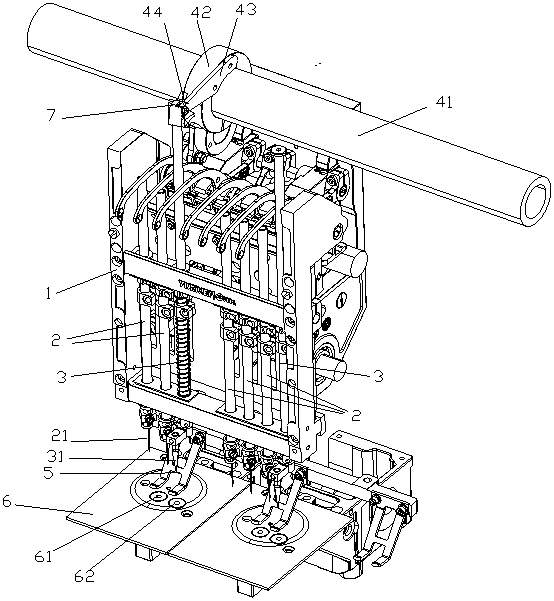
[0034] refer to figure 1 , this implementation case is used for the independent carving system of the embroidery machine, including the needle bar frame 1, the needle bar, and the driving system for carving holes. The needle bar frame 1 can translate left and right, and all the needle bars are installed on the needle bar frame 1. In this embodiment, this independent carving system is set as a "4+3" structural mode, The right side of the needle bar frame 1 is set: "4" bar, and the left side of the needle bar frame 1 is set with "3" bar, and the "4" bar is used to execute the following 4 colors (including 4 colors) For multi-color embroidery, the "3" bar is used to perform multi-color embroidery of less than 3 colors (including 3 colors). "3" bar and "4" bar, select the needle bar assembly carving knife 31 located on the far right as the hole carving bar, which is denoted as needle bar 3 here, and other needle bar assembly embroidery needles 21 are denoted as needle bar here. ...

Embodiment example 2

[0042] In this implementation case, except that the installation methods of the needle bar 3 and the carving knife 34 are different, the others are the same as the implementation case 1. refer to Figure 6 , in this implementation case, the bottom end of the needle bar 3 is directly equipped with a carving knife 34. Compared with the implementation case 1, the space at the bottom of the needle bar 3 is more abundant, which is beneficial to the overall structural adjustment, and at the same time does not Affect the removal of the carving knife 34 and replace it with an embroidery needle.

Embodiment example 3

[0044] In this implementation case, except that the return spring is different in the connection relation of the needle bar, the others are the same as the implementation case 1. refer to Figure 7 , in this implementation case, the needle bar 3 is provided with a return spring 3-B, the return spring 3-B, and the two ends of the return spring 3-B are respectively connected to the top of the needle bar 3 and the needle Mid-range 12 for rod holders. Likewise, the connection mode between the needle bar 2 and the back-moving spring is the same.


PUM


Abstract

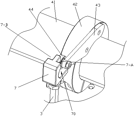
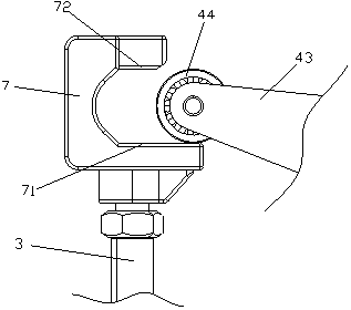
The invention discloses an independent hole carving system for an embroidery machine. The independent hole carving system comprises a needle bar frame and a plurality of needle bars installed on the needle bar frame, wherein the needle bar frame can horizontally move left and right. The independent hole carving system further comprises a hole carving driving system which is not connected with anyneedle bar, the needle bar frame can horizontally move left and right, a hole carving knife is assembled at the bottom end of any one of the needle bars, a driven part is assembled at the top end of each needle bar, the needle bars with the driven parts can move to a driving position of the hole carving driving system, and the hole carving driving system can act on the driven parts and drive the needle bars to move downwards to the maximum stroke and then drives the needle bars to completely reset or semi-reset. The independent hole carving system has the beneficial effects that the needle bars can be randomly selected to assemble the hole carving knifes for hole carving, and hole carving and multi-color embroidery are both considered.

Description

technical field [0001] The invention relates to an engraving system, especially an independent engraving system for an embroidery machine. Background technique [0002] In the embroidery machine industry, the two operations of embroidery and engraving on embroidery are frequently used. In the prior art, both the engraving bar and the needle bar are driven by the same drive shaft. This engraving mode Limited by the driving mode of the drive shaft, the movement stroke and frequency of the engraving rod and the needle bar are the same, and then the engraving depth and the engraving frequency of the engraving knife cannot be changed according to the actual engraving requirements. The way of carving holes is relatively simple, and the effect of carving holes is also poor. [0003] In view of the above problems, the carving rod can be provided with a separate driving system, which is separated from the driving of the needle rod. For example, the publication number CN105019163B di...

Claims


Application Information

Patent Timeline
IPC IPC(8): D05C7/10
CPCD05C7/10
Inventor 陈天龙方狄永蔡洁钟
Owner 浙江镨美科智能刺绣设备有限公司
Learn More