Tool coordinate system calibration method and device for three-axis mechanical arm

A technology of tool coordinate system and calibration method, applied in the field of tool coordinate system calibration, can solve the problems of unfavorable field application, difficult to guarantee accuracy, time-consuming and energy-consuming, etc.

Active Publication Date: 2020-06-16
DELTA ELECTRONICS JIANGSU
View PDF12 Cites 0 Cited by
  • Summary
  • Abstract
  • Description
  • Claims
  • Application Information

AI Technical Summary

Problems solved by technology

Using the conventional method to calibrate the tool coordinate system is done manually by the operator, and the accuracy is difficult to guarantee. It often needs to go through multiple calibrations to obtain the calculation result with the smallest error, which consumes a lot of time a...

Method used


Image

  • Tool coordinate system calibration method and device for three-axis mechanical arm
  • Tool coordinate system calibration method and device for three-axis mechanical arm
  • Tool coordinate system calibration method and device for three-axis mechanical arm

Examples


Embodiment Construction

[0063] Example embodiments will now be described more fully with reference to the accompanying drawings. Example embodiments may, however, be embodied in many forms and should not be construed as limited to the embodiments set forth herein. Rather, these embodiments are provided so that this disclosure will be thorough and complete, and will fully convey the concept of the example embodiments to those skilled in the art. The same reference numerals denote the same or similar structures in the drawings, and thus their repeated descriptions will be omitted.

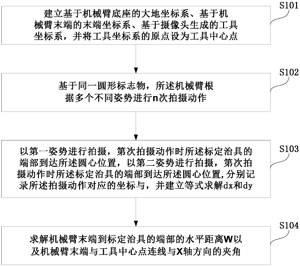
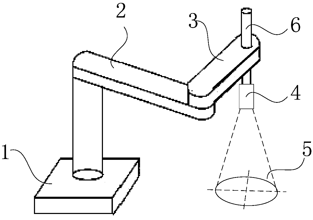
[0064] figure 1 It is a schematic flowchart of the calibration method of the tool coordinate system of the three-axis manipulator of the present invention. figure 2 It is a schematic diagram of the tool coordinate system calibration device of the three-axis mechanical arm of the present invention. like figure 1 and 2 As shown, the present invention provides a method for calibrating the tool coordinate system of a thre...


PUM


Abstract

The invention provides a tool coordinate system calibration method and device for a three-axis mechanical arm. The calibration method comprises the following steps of enabling a mechanical arm to carry out the nth photographing actions according to a plurality of different postures based on the same circular marker, and carrying out the photographing in a first posture, photographing in a second posture when the end part of a calibration jig reaches the circle center position in the ith photographing action, correspondingly recording coordinates OEi and OEj corresponding to the tail end of themechanical arm in the jth photographing action when the end part of the calibration jig reaches the circle center position, and establishing an equation for solving, finally, obtaining the horizontaldistance W between the tail end of the mechanical arm and the end of the calibration jig and the included angle theta between a connecting line of the tail end of the mechanical arm and the tool center point and the X-axis direction of a coordinate system at the tail end of the mechanical arm. According to the calibration method, the calibration process is greatly simplified, and the calibrationprecision is guaranteed through visual use.

Description

technical field [0001] The invention relates to the field of tool coordinate system calibration, in particular to a tool coordinate system calibration method and a calibration device of a three-axis mechanical arm. Background technique [0002] In industrial production lines, special parts are usually fixed at the end of the mechanical arm of the industrial robot as tools, such as fixtures, welding torches and other devices. A coordinate system is usually established at a fixed position on these tools, the so-called tool coordinate system. The trajectory planning of the robot is usually planned for a certain point of the tool after the above-mentioned tools are added, and this point is usually called the Tool Center Point (TCP: Tool Center Point). Under normal circumstances, the origin of the tool coordinate system is the TCP. After the tool is installed on the end of the robot's mechanical arm, unless its installation position is artificially changed, the tool coordinate sy...

Claims


Application Information

Patent Timeline
IPC IPC(8): B25J9/16
CPCB25J9/1653B25J9/1656
Inventor 颜良益张鑫伍蒙张曼
Owner DELTA ELECTRONICS JIANGSU
Why Eureka
Try Eureka