A high-efficiency continuous coated sand mixing device

A continuous type, coated sand technology, applied in foundry molding equipment, machinery for cleaning/processing of casting materials, metal processing equipment, etc. High efficiency and good sand mixing effect

Active Publication Date: 2021-08-17
亚威新材料(徐州)有限公司
View PDF6 Cites 0 Cited by
  • Summary
  • Abstract
  • Description
  • Claims
  • Application Information

AI Technical Summary

Problems solved by technology

[0003] In the prior art, when the coated sand is mixed, the main material and the ingredients are usually concentrated in the mixing tank, and the tank is equipped with a stirring device for stirring, and the main material and the ingredients are mixed evenly. This sand mixing method There are defects such as long sand mixing time and poor sand mixing effect

Method used


Image

  • A high-efficiency continuous coated sand mixing device
  • A high-efficiency continuous coated sand mixing device
  • A high-efficiency continuous coated sand mixing device

Examples


Embodiment 1

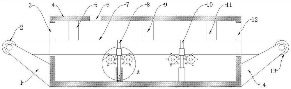
[0024] see Figure 1-3 , the present embodiment provides a high-efficiency continuous coated sand sand mixing device, comprising a box 4, one side of the box 4 is provided with a feed port 3, and the other side is provided with a discharge port 12, the box 4 A first pulley 2 is arranged on the outside of one side of the feed opening 3, and a second pulley 13 is arranged on the outside of the side of the box body 4 located at the discharge opening 12. The first pulley 2 and the first pulley 2 The second pulley 13 is sleeved and connected by a conveyor belt 7, and the conveyor belt 7 runs through the box body 4 from the feed port 3 and the discharge port 12; the upper part of the box body 4 is close to the feed port One side of the feed port 3 is provided with a batching inlet 6, and the inside of the box body 4 is provided with a first uniform material assembly 5, a second uniform material assembly 9 and a third uniform material assembly 11 at intervals along the direction of t...

Embodiment 2

[0039] see figure 1 , a high-efficiency continuous coated sand sand mixing device. Compared with Embodiment 1, the first pulley 2 is connected to the side wall of the box body 4 through the first bracket 2, and the second belt pulley The wheel 13 is connected with the side wall of the box body 4 through the second bracket 14 .

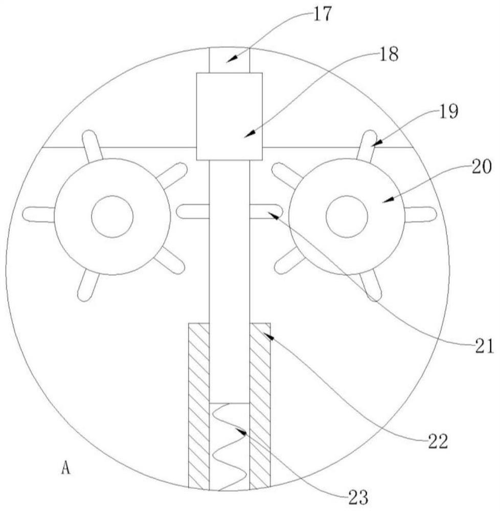
[0040] The embodiment of the present invention can realize the continuous and efficient sand mixing operation of coated sand, and has the advantages of high sand mixing efficiency and good sand mixing effect. into the box 4, the sand mixing main material is evenly spread on the upper part of the conveyor belt 7 when passing through the first homogenizing component 5, and then the sand mixing ingredients are put into the box 4 from the batching inlet 6 to mix with the sand mixing main material , use the first elastic component 8 to act on the bottom of the conveyor belt 7, thereby driving the conveyor belt 7 to vibrate, so that the main ingredient of t...


PUM


Abstract

The invention provides a high-efficiency continuous coated sand mixing device, which belongs to the technical field of coated sand processing, and includes a box body, one side of the box body is provided with a material inlet, and the other side is provided with a discharge port. A first pulley is arranged outside the side of the body located at the feed inlet, and a second pulley is arranged outside the side of the box located at the discharge opening, and the first pulley and the second pulley The conveyor belt is sleeved and connected between them, and the conveyor belt runs through the box from the feeding port and the discharging port; an ingredient inlet is opened on the side of the upper part of the box close to the feeding port, and the box body A first homogenizing assembly, a second homogenizing assembly and a third homogenizing assembly are arranged at intervals along the direction of the conveyor belt inside, and the first homogenizing assembly is located between the material inlet and the ingredient inlet. The embodiment of the present invention can realize the continuous and efficient sand mixing operation of coated sand, and has the advantages of high sand mixing efficiency and good sand mixing effect.

Description

technical field [0001] The invention belongs to the technical field of coated sand processing, in particular to a high-efficiency continuous coated sand mixing device. Background technique [0002] The coated sand mainly uses high-quality selected natural quartz sand as raw sand, thermoplastic phenolic resin, urotropine and reinforcing agent as raw materials. According to the different technical requirements of users, the ratio should be adjusted appropriately in terms of curing speed, release property, fluidity, collapsibility, surface finish of castings, storage, etc. It is one of the best molding materials for automobiles, tractors, hydraulic parts, etc. [0003] In the prior art, when the coated sand is mixed, the main material and the ingredients are usually concentrated in the mixing tank, and the tank is equipped with a stirring device for stirring, and the main material and the ingredients are mixed evenly. This sand mixing method There are defects such as long san...

Claims


Application Information

Patent Timeline
Patent Type & Authority Patents(China)
IPC IPC(8): B22C5/04
CPCB22C5/0472B22C5/0477B22C5/0481
Inventor 郭威王永伟冯波张青山
Owner 亚威新材料(徐州)有限公司
Why Eureka
Try Eureka