
A segmented charging method for electronic detonators in a networking state and electronic detonator networking

An electronic detonator and segmented charging technology, which is applied to battery circuit devices, current collectors, electric vehicles, etc., can solve the problems of long charging time, increased charging, and long charging time intervals, so as to reduce repeated state processing and ensure capacitor voltage value, the effect of saving charging time

Active Publication Date: 2021-07-20
杭州晋旗电子科技有限公司
View PDF9 Cites 0 Cited by
  • Summary
  • Abstract
  • Description
  • Claims
  • Application Information

AI Technical Summary

Problems solved by technology

[0003] When the number of electronic detonators in the network is large, the charging time is long, and the charging time interval between the first and the last two electronic detonators is longer, and each electronic detonator needs to be operated separately, which increases the probability of failure to detonate when the charge is not enough; The charging voltage is judged by the first detection, and the whole voltage division is used for charging. The charging voltage at each stage must control the charging current. If the voltage division method is adopted, the operation instructions are extremely complicated, the charging process is more cumbersome, and the charging time is longer. Homework adds more uncertainties

Method used


Image

  • A segmented charging method for electronic detonators in a networking state and electronic detonator networking
  • A segmented charging method for electronic detonators in a networking state and electronic detonator networking

Examples


Embodiment 1

[0034] Such as figure 1 As shown, this embodiment provides a segmented charging method for electronic detonators in a networking state. The segmented charging method for electronic detonators is used to charge the capacitors of electronic detonators in the electronic detonator network. The electronic detonators also include a charging switch. The switch is connected in series with the capacitor, and when the capacitor is charged, the charging switch is closed. The electronic detonator network includes n electronic detonators connected in parallel to the same electronic detonator detonator, and each electronic detonator is numbered 1 to n in turn. Before charging the capacitor of the electronic detonator, a preset voltage should be set on the capacitor as a basis for judging whether the capacitor is fully charged: when the charging voltage of the capacitor reaches the preset voltage, the capacitor is fully charged.

[0035] The electronic detonator section charging method comp...

Embodiment 2

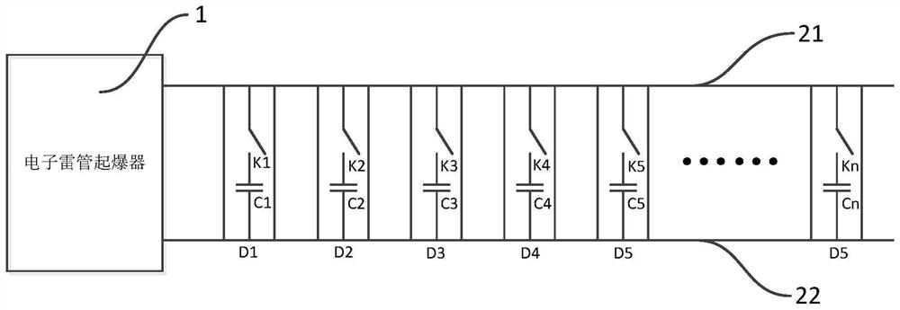
[0045] Such as figure 2 As shown, the present embodiment provides a network of electronic detonators, including an electronic detonator initiator 1, a bus bar, an electronic detonator D1 to an electronic detonator Dn, and each electronic detonator includes a capacitor and a charging switch, that is, a capacitor C1 to a capacitor Cn, The charging switch K1 to the charging switch Kn, in each electronic detonator, the capacitor and the charging switch are connected in series; the bus bar includes the positive pole of the bus bar 21 and the negative pole of the bus bar 22, and the electronic detonator D1 to the electronic detonator Dn are connected in parallel to the electronic detonator through the positive pole of the bus bar 21 and the negative pole of the bus bar 22. 1, the capacitor C1 and the charging switch K1 are connected in series between the bus positive pole 21 and the bus negative pole 22, the capacitor C2 and the charging switch K2 are connected in series between the...


PUM


Abstract

The invention discloses a segmented charging method for electronic detonators in a networking state and electronic detonator networking, relates to the technical field of electronic detonators, and is used for charging the capacitance of electronic detonators in the electronic detonator networking, including the following steps: Choose one of the capacitors from 2 to n‑1, charge the selected capacitor to n capacitors; choose one of the uncharged capacitors, charge the selected capacitor to n capacitors; repeat the previous Steps until the capacitors numbered 1 to n are all charged. The method provided by the invention not only shortens the charging time, but also does not need cumbersome operation instructions under the premise of ensuring the blasting probability.

Description

【Technical field】 [0001] The invention relates to the technical field of electronic detonators, in particular to a segmented charging method for electronic detonators in a networking state and a network of electronic detonators. 【Background technique】 [0002] With the continuous development and improvement of electronic detonator technology, its technical superiority has been more and more widely recognized in the global blasting industry. The principle of detonation is to operate the electronic detonator chip to charge the energy storage capacitor through control instructions. After charging is completed The primer is ignited by a discharge to the bridge wire. In the prior art, the communication between the detonator and the electronic detonator mainly adopts parallel connection. Due to the limited output power of the detonator, if there are too many electronic detonators connected to the detonator, the excessive current will exceed the limit of the detonator output when ...

Claims


Application Information

Patent Timeline
Patent Type & Authority Patents(China)
IPC IPC(8): H02J7/34F42D1/045
CPCF42D1/045H02J7/345
Inventor 李叶磊王斐
Owner 杭州晋旗电子科技有限公司
Learn More