
Alternating-current high-voltage vacuum arc-extinguishing chamber

A vacuum interrupter, high-voltage technology, applied in high-voltage air circuit breakers, high-voltage/high-current switches, electrical components, etc., can solve the problems of poor vacuum interrupter safety, shortened arc interrupter service life, and short service life. , to achieve the effect of prolonging service life, stable installation and shortening service life

Inactive Publication Date: 2020-06-12
湖北久歌电气有限公司
View PDF0 Cites 2 Cited by
  • Summary
  • Abstract
  • Description
  • Claims
  • Application Information

AI Technical Summary

Problems solved by technology

[0006] The present invention aims to solve the technical problems of poor safety and short service life of the existing vacuum interrupter, and provides an AC high-voltage vacuum interrupter. The device can form small compartments that can The evaporation of the electrode metal and the splashing of the liquid droplets generated when the moving contact is separated from the static contact are carried out to avoid the evaporation of the electrode metal and the splashing of the liquid droplets directly in contact with the shielding cover, so that the shielding cover is excessively corroded and shortened The service life of the arc chamber has a wide range of practicability

Method used


Image

  • Alternating-current high-voltage vacuum arc-extinguishing chamber
  • Alternating-current high-voltage vacuum arc-extinguishing chamber
  • Alternating-current high-voltage vacuum arc-extinguishing chamber

Examples


Embodiment Construction

[0024] The following will clearly and completely describe the technical solutions in the embodiments of the present invention with reference to the accompanying drawings in the embodiments of the present invention. Obviously, the described embodiments are only some, not all, embodiments of the present invention. Based on the embodiments of the present invention, all other embodiments obtained by persons of ordinary skill in the art without making creative efforts belong to the protection scope of the present invention.

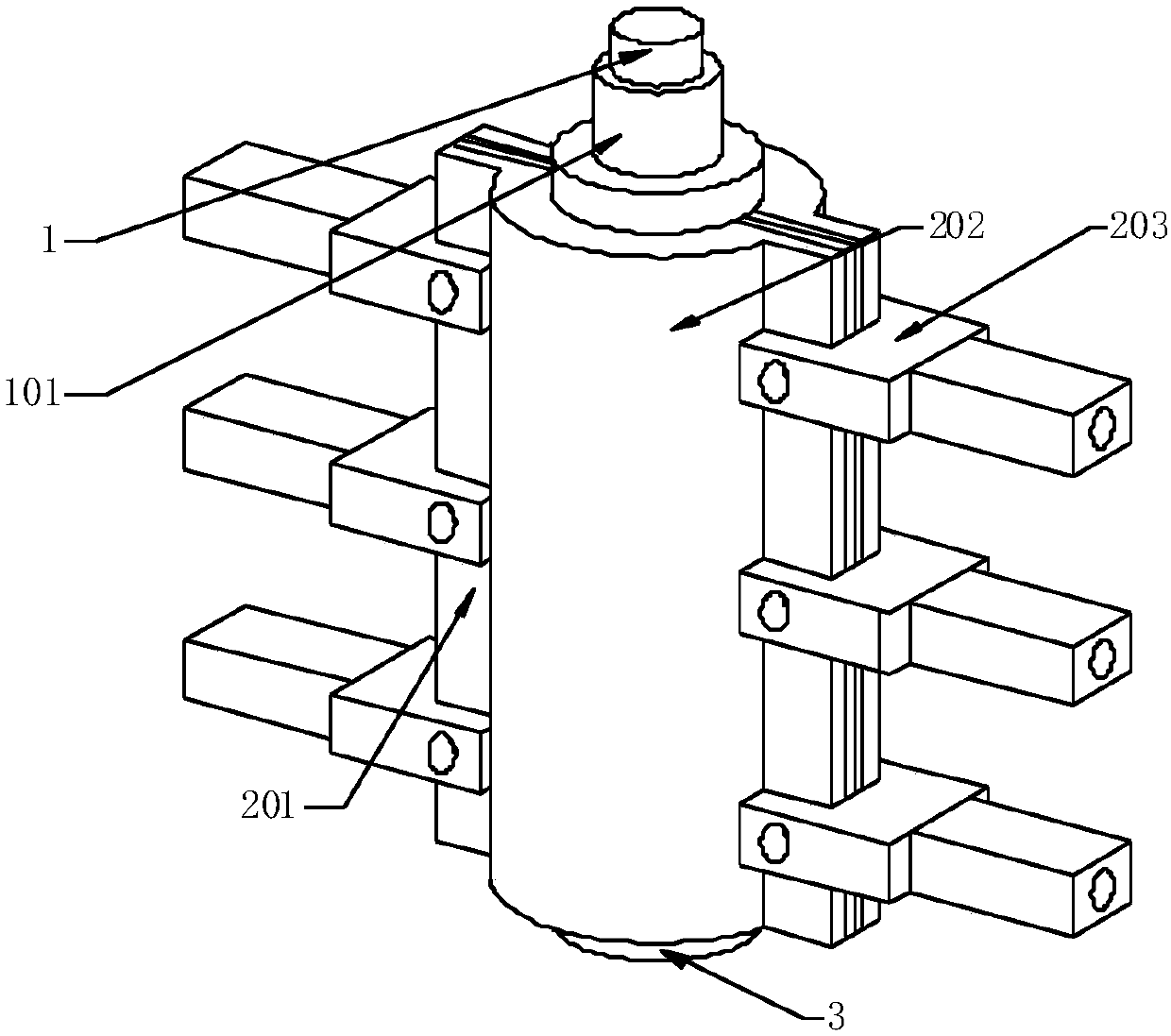
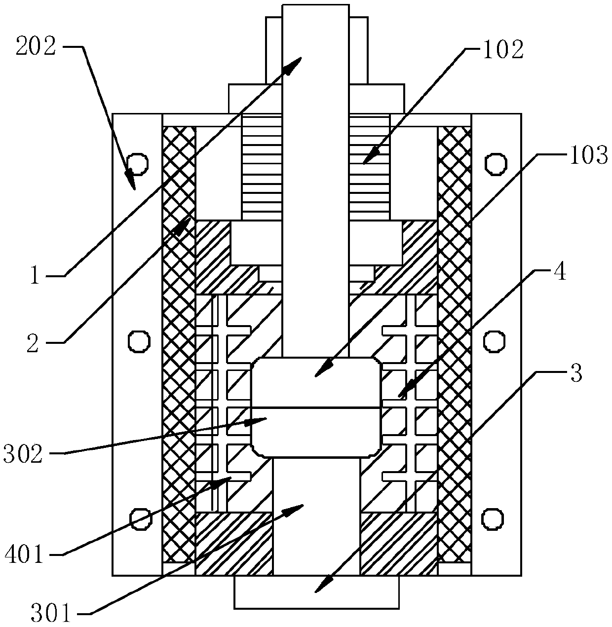
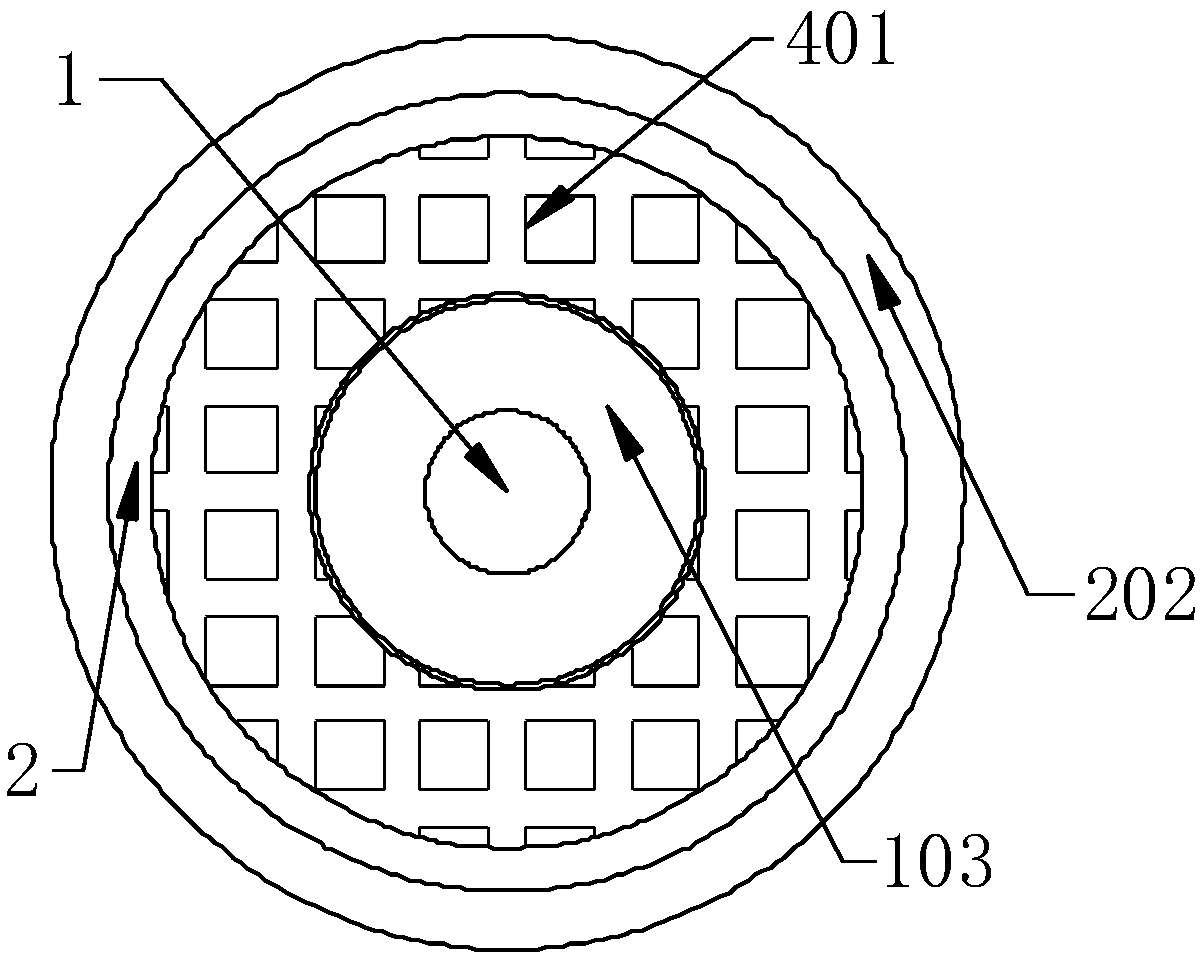
[0025] The moving rod 1, the moving contact 103, the porcelain shell 2, the side fixed plate 201, the sealing shell 202, the fixed block 203, the static contact 302, the shielding cover 4, and the baffle plate 401 used in the present invention can all be purchased through the market Or private custom income.

[0026] Please refer to Figures 1-3. In the embodiment of the present invention, an AC high-voltage vacuum interrupter includes a porcelain case 2 and a ...


PUM


Abstract

The invention provides an alternating-current high-voltage vacuum arc-extinguishing chamber. The chambercomprises a porcelain shell and a sealing shell, the periphery of the porcelain shell is wrappedwith thesealing shell; the head end of a moving rod penetrates through the top of the porcelain shell; a moving contact is fixedly arranged at the bottom end of the moving rod; the periphery of the moving rod is sleeved with a guide sleeve, one side of the guide sleeve is fixedly connected with the sealing shell, a corrugated pipe is arranged below the guide sleeve, one end of the corrugated pipeis fixedly arranged on the inner wall of the porcelain shell, a static contact is attached to the lower end face of the moving contact, a static rod is fixedly arranged on the lower end face of the static contact, and a static cover plate is fixedly connected to the lower end face of the static rod. Evaporation and droplet splashing of electrode metal generated when the moving contact is separated from the static contact can be received by small compartments formed by the flow resisting plates. Evaporation of electrode metal and direct contact of liquid drop splashing with the shielding caseare avoided, the service life of the arc extinguish chamber is shortened due to excessive corrosion of the shielding case, and the chamber is suitable for production and use of the alternating-currenthigh-voltage vacuum arc-extinguishing chamber and has a good development prospect.

Description

technical field [0001] The invention relates to the technical field of electrical devices, in particular to a vacuum interrupter. Background technique [0002] Vacuum interrupter is an electrical device for power supply and distribution. It is suitable for high-voltage power supply and distribution line switches for breaking current. The current technical considerations are not comprehensive, and it has the following disadvantages: [0003] 1. There are no other protective components around the arc extinguishing chamber, so that the arc extinguishing chamber exposed to the outside world for a long time will be eroded, causing the outer wall of the arc extinguishing chamber to become more fragile, resulting in poor safety of the arc extinguishing chamber. [0004] 2. There are no other stable components around the arc extinguishing chamber, so the arc extinguishing chamber is easily disturbed by the outside world, causing the arc extinguishing chamber to shake frequently and ...

Claims


Application Information

Patent Timeline
IPC IPC(8): H01H33/664H01H33/662
CPCH01H33/662H01H33/664
Inventor 刘唯一郭庆忠
Owner 湖北久歌电气有限公司
Learn More