Urban roadway curbstone drainage ditch structure
A drainage ditch and curb stone technology, applied in drainage structures, roads, roads, etc., can solve the problems of weak drainage capacity and easy accumulation of water, and achieve the effect of smooth drainage channels, improved drainage, and convenient cleaning.
- Summary
- Abstract
- Description
- Claims
- Application Information
AI Technical Summary
Problems solved by technology
Method used
Image
Examples
Embodiment 1
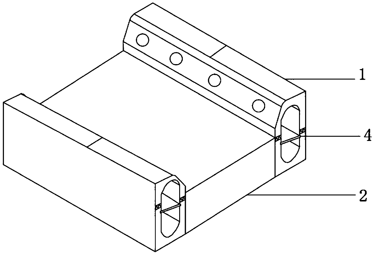
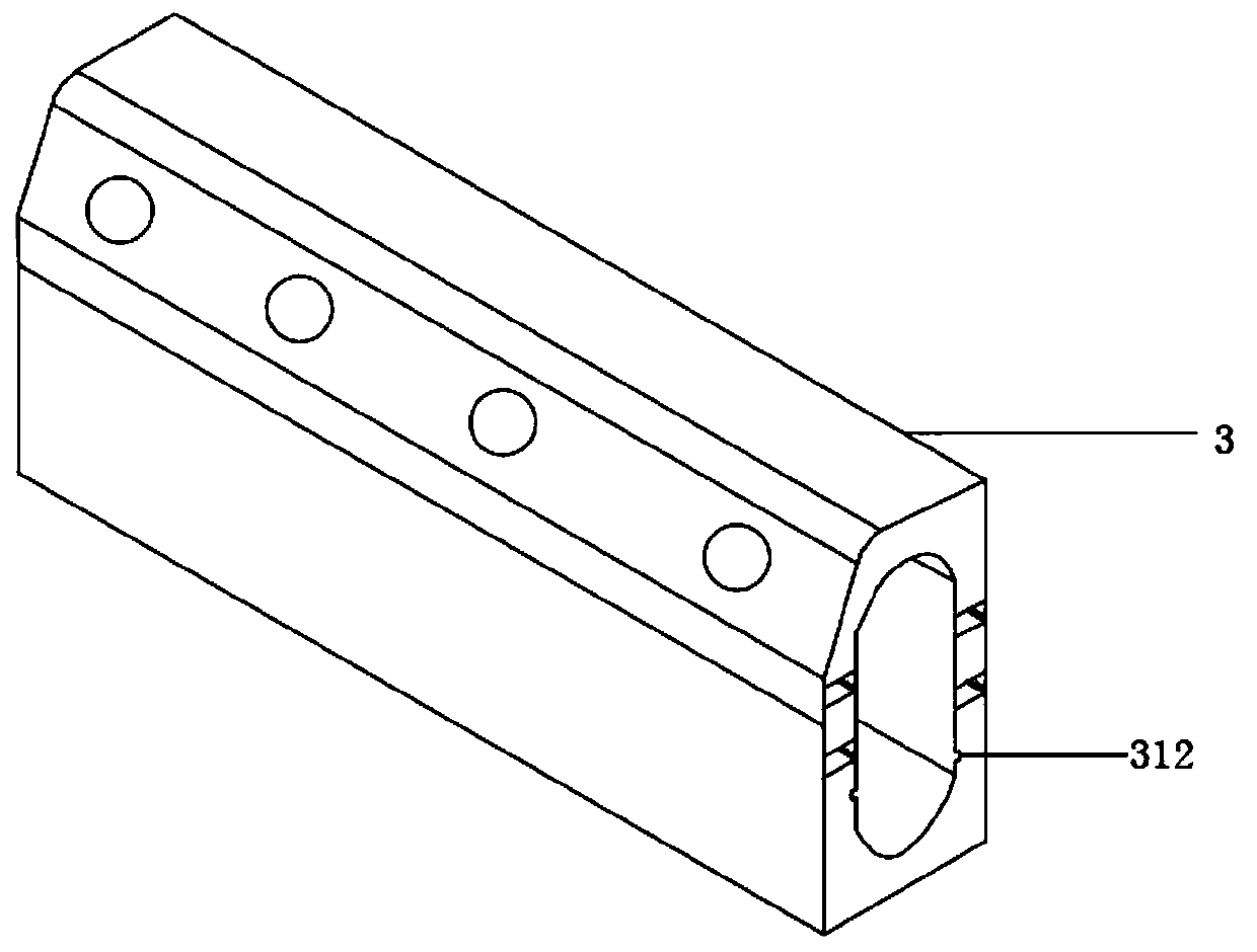
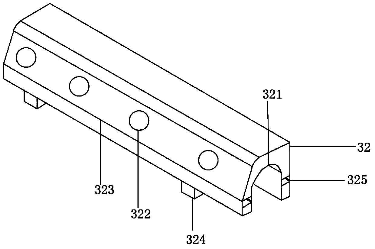
[0027] see Figure 1 to Figure 6 , the figure shows a city road calculus drainage ditch structure provided by Embodiment 1 of the present invention, which includes: a curb drainage ditch 1 and a roadway 2, and curbstones are respectively arranged on both sides of the roadway 2 Drainage ditch 1, curb drainage ditch 1 is composed of several curbstones 3, curbstone 3 includes a drainage member 31 and a top cover 32, a hollow first cavity 311 is arranged inside the drainage member 31, and the first cavity 311 drains water along the The length direction of the first cavity 31 of the component is set, and the top cover 32 is fixedly installed on the top of the drainage component 31. A hollow second cavity 321 is arranged inside the top cover 32, and the first cavity 311 and the second cavity 321 are combined. Finally, a drainage channel is formed for drainage. The top cover 32 is provided with several drainage holes 322 towards the side of the roadway 2. The drainage holes 322 are e...
Embodiment 2
[0037] see Figure 1 to Figure 6, the figure shows a kind of calculus drainage ditch structure for urban vehicle roads provided by Embodiment 2 of the present invention. On the basis of the above-mentioned embodiments, this embodiment further makes the following technical solutions as improvements: drainage components Slide grooves 312 are respectively provided on the two inner sidewalls of 31, and the second filter component 4 is slidably connected in the slide grooves 312, and the first filter component and the second filter component 4 are filter nets. A second filter screen is arranged between the top cover and the drainage member, which can filter sundries again, so that the drainage channel is unimpeded, and the drainage capacity is improved.
Embodiment 3
[0039] see Figure 1 to Figure 6 , the figure shows a city traffic road stone drainage ditch structure provided by Embodiment 3 of the present invention. On the basis of the above-mentioned embodiments, this embodiment further makes the following technical solutions as improvements: top cover 32 is provided with an inclined surface 323 , the inclined surface 323 is located on the side of the roof 32 facing the roadway 2 , and the drainage hole 322 is arranged on the inclined surface 323 . Through the setting of the above structure, the slope can make the water flow into the drainage hole quickly, so as to improve the drainage effect. At the same time, there are many vehicles on the roadway, which are easy to collide with the drainage ditch. The upper part of the drainage ditch is set as a slope, which can reduce the damage caused. .
PUM
 Abstract
Description
Claims
Application Information
 - R&D
- Intellectual Property
- Life Sciences
- Materials
- Tech Scout
- Unparalleled Data Quality
- Higher Quality Content
- 60% Fewer Hallucinations
Browse by: Latest US Patents, China's latest patents, Technical Efficacy Thesaurus, Application Domain, Technology Topic, Popular Technical Reports.
© 2025 PatSnap. All rights reserved.Legal|Privacy policy|Modern Slavery Act Transparency Statement|Sitemap|About US| Contact US: help@patsnap.com


