
Water attack angle forward-inclined ultra-high-speed cruise rescue speedboat

An ultra-high-speed, water-attacking technology, which is applied to lifesaving in water, ships, and ship safety. It can solve problems such as large disturbances, drastic changes in force, and unstable driving, so as to increase the axial exit speed and improve working conditions. , the effect of increasing the driving speed

Active Publication Date: 2020-06-12
济宁三泰和游艇制造有限公司
View PDF8 Cites 4 Cited by
  • Summary
  • Abstract
  • Description
  • Claims
  • Application Information

AI Technical Summary

Problems solved by technology

[0003] When a speedboat traveling at high speed breaks through the water in front of it, it will experience greater resistance, and the bow is raised, making it unstable in a large wave environment; moreover, the structure with the propeller behind, because the bottom of the hull squeezes out the water, Therefore, the water entering the propeller is gathered from both sides into the area between the propeller and the stern, and then pumped by the propeller. When driving fast, the disturbance is large and the water flow is turbulent. The operating condition of the propeller is very poor and it is easy to be damaged. , running poorly
[0004] Traditional steering is accomplished through the steering rudder at the tail. When driving at high speed, if the position of the steering rudder is suddenly changed, it is prone to drastic changes in force, affecting driving stability, and even capsizing

Method used


Image

  • Water attack angle forward-inclined ultra-high-speed cruise rescue speedboat
  • Water attack angle forward-inclined ultra-high-speed cruise rescue speedboat
  • Water attack angle forward-inclined ultra-high-speed cruise rescue speedboat

Examples


Embodiment Construction

[0034] The following will clearly and completely describe the technical solutions in the embodiments of the present invention with reference to the accompanying drawings in the embodiments of the present invention. Obviously, the described embodiments are only some, not all, embodiments of the present invention. Based on the embodiments of the present invention, all other embodiments obtained by persons of ordinary skill in the art without making creative efforts belong to the protection scope of the present invention.

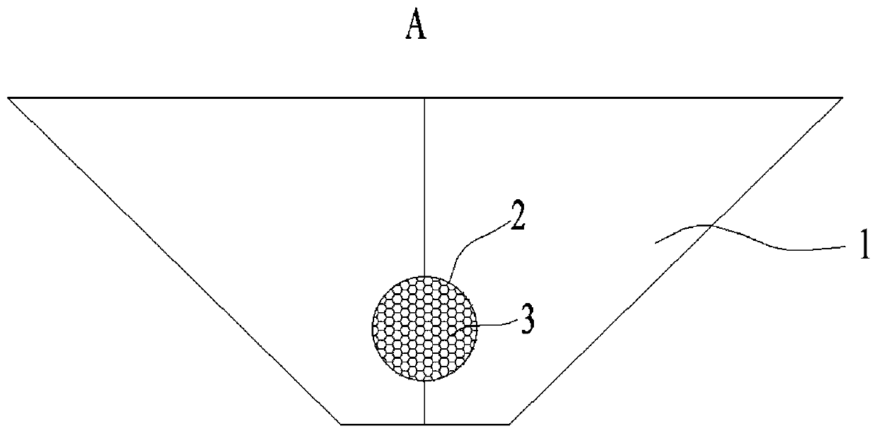
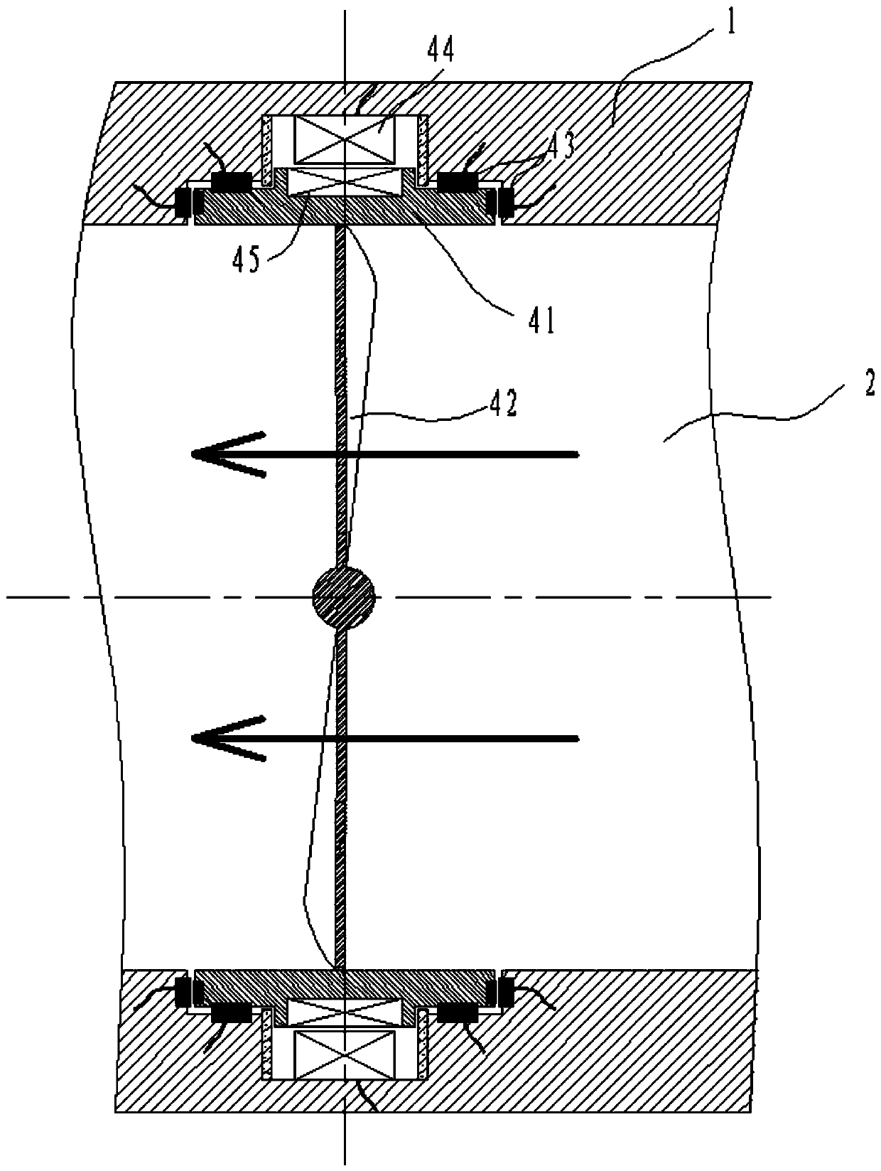
[0035] Such as figure 1As shown, a forward-leaning ultra-high-speed cruising rescue speedboat, the speedboat includes a hull 1, a waterway 2 and a propulsion pump 4, the bottom of the hull 1 is provided with a waterway 2 parallel to its own axis, and the inner path of the waterway 2 is provided with a propulsion pump. pump4.

[0036] The waterway 2 is used as the water inlet and outlet channel, and the propulsion pump 4 installed in the waterway 2 can also pl...


PUM


Abstract

The invention discloses a water attack angle forward-inclined ultra-high-speed cruise rescue speedboat. The speedboat comprises a speedboat body, a water channel and a propelling pump, the water channel parallel to the axis of the speedboat body is arranged at the bottom of the speedboat body, and the propelling pump is arranged on an internal path of the water channel. The propelling pump comprises a seat ring, axial flow blades, a magnetic bearing, a stator and a rotor. An annular groove is formed in the water channel, the seat ring is arranged in the groove through the magnetic bearing, theaxis of the seat ring coincides with that of the water channel, a plurality of axial flow blades which are circumferentially and uniformly distributed are mounted on the inner ring of the seat ring,the axial flow blades are fan-shaped about the axis of the seat ring and extend towards the axis direction of the seat ring, all the axial flow blades extend to the axis of the seat ring and then arespot-welded together, the rotor is fixedly installed on the outer ring of the seat ring, the stator is fixed to the inner wall of the water channel and faces the rotor, the magnetic bearings are installed on the seat ring and the inner wall of the water channel in pairs, and the magnetic bearings are arranged in the axial direction and the radial direction of the axis of the water channel.

Description

technical field [0001] The invention relates to the field of speed boats, in particular to a super-high-speed cruising and rescue speed boat with an angle of attack forward. Background technique [0002] The speedboat is a kind of water-going boat, which travels fast and is often used for surface emergency command and rescue. [0003] When a speedboat traveling at high speed breaks through the water in front of it, it will experience greater resistance, and the bow is raised, making it unstable in a large wave environment; moreover, the structure with the propeller behind, because the bottom of the hull squeezes out the water, Therefore, the water entering the propeller is gathered from both sides into the area between the propeller and the stern, and then pumped by the propeller. When driving fast, the disturbance is large and the water flow is turbulent. The operating condition of the propeller is very poor and it is easy to be damaged. , poor operating conditions. [00...

Claims


Application Information

Patent Timeline
IPC IPC(8): B63C9/02B63H11/04B63B1/32
CPCB63C9/02B63H11/04B63B1/32Y02T70/10
Inventor 何凡
Owner 济宁三泰和游艇制造有限公司
Learn More