
Water tank and cleaning equipment

A technology of water tanks and horizontal sections, applied in cleaning equipment, cleaning machinery, carpet cleaning, etc., can solve the problems of air hole blockage, loss of ventilation function, etc., and achieve the effect of simple structure, convenient and fast structure

Pending Publication Date: 2020-06-12
DREAM INNOVATION TECH (SUZHOU) CO LTD
View PDF0 Cites 1 Cited by
  • Summary
  • Abstract
  • Description
  • Claims
  • Application Information

AI Technical Summary

Problems solved by technology

However, the air intake hole of a general flat-panel drag is directly arranged on the shell of the flat-panel drag. After use, it is placed upright or upside down according to the position of use, and the air holes provided on it are easily blocked by free-falling dust or particles. Clogged after covering, thus losing the ventilation function

Method used


Image

  • Water tank and cleaning equipment
  • Water tank and cleaning equipment
  • Water tank and cleaning equipment

Examples


Embodiment Construction

[0028] The technical solutions of the present invention will be clearly and completely described below in conjunction with the accompanying drawings. Obviously, the described embodiments are part of the embodiments of the present invention, rather than all of them. Based on the embodiments of the present invention, all other embodiments obtained by those of ordinary skill in the art without creative work shall fall within the protection scope of the present invention.

[0029] In the description of the present invention, it should be noted that the terms "center", "upper", "lower", "left", "right", "vertical", "horizontal", "inner", "outer", etc. The indicated orientation or positional relationship is based on the orientation or positional relationship shown in the drawings, and is only for the convenience of describing the present invention and simplifying the description, rather than indicating or implying that the mechanism or element referred to must have a specific orientatio...


PUM

PropertyMeasurementUnit
Diameteraaaaaaaaaa

Abstract

The invention relates to a water tank and cleaning equipment. A water storage space is arranged in the water tank, and the water tank further comprises at least one drainage hole communicated with thewater storage space and an exhaust assembly; the exhaust assembly comprises a through hole communicated with the atmosphere, at least one air inlet hole communicated with the water storage space andan air inlet channel used for communicating the air inlet hole with the through hole, wherein the diameter of the through hole is larger than that of the air inlet hole. The exhaust assembly is arranged in the water tank and comprises the air inlet hole communicated with the water storage space, so that the problem that the air inlet hole is covered and blocked by freely falling dusts or particleswhen the water tank or the cleaning equipment is horizontally placed or reversely placed is avoided, and the structure is simple, and convenient and rapid effects are achieved.

Description

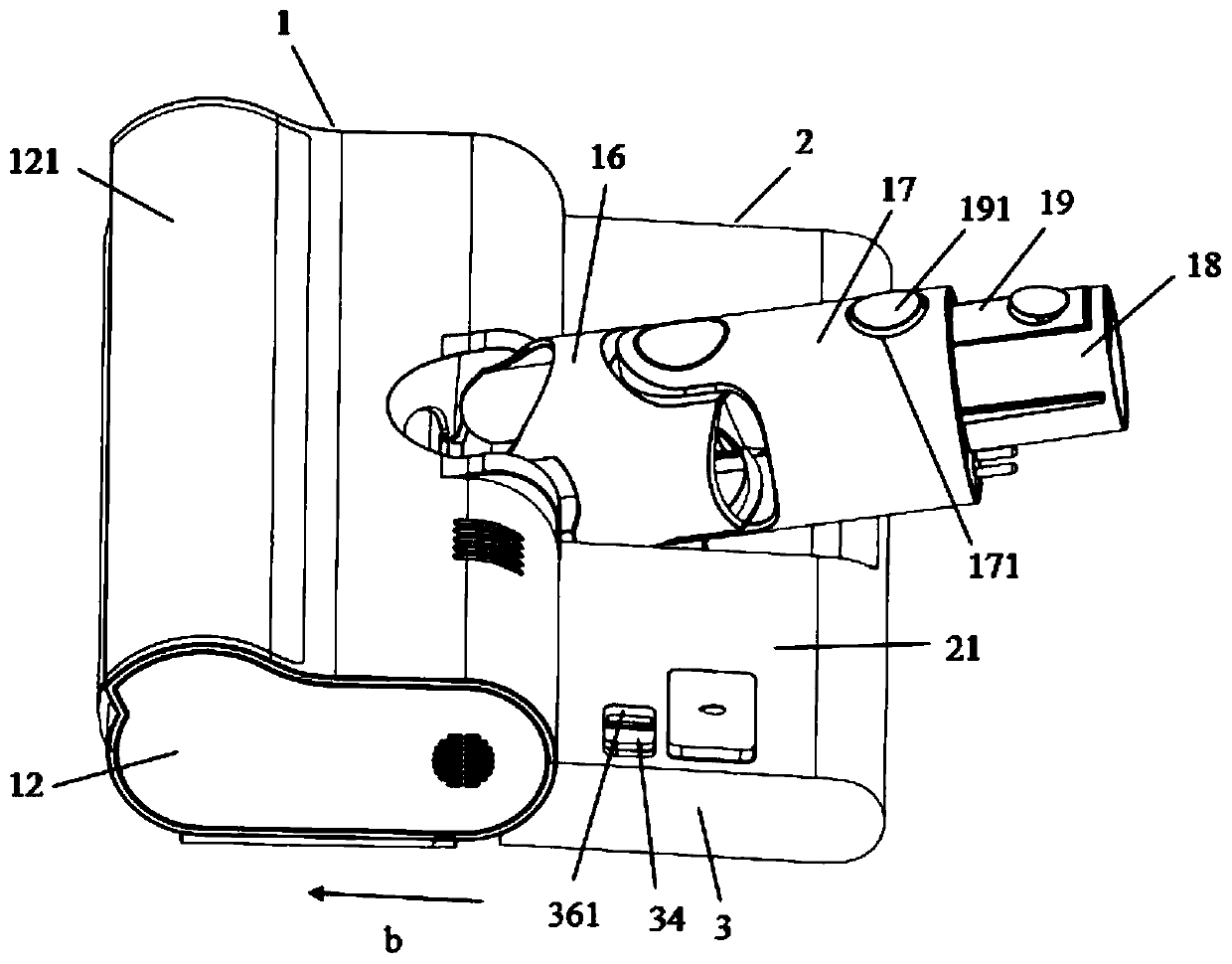
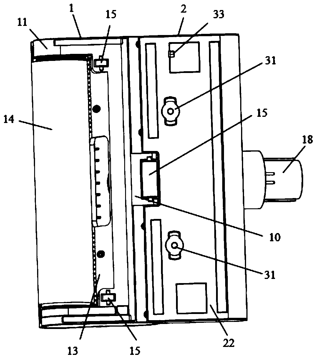
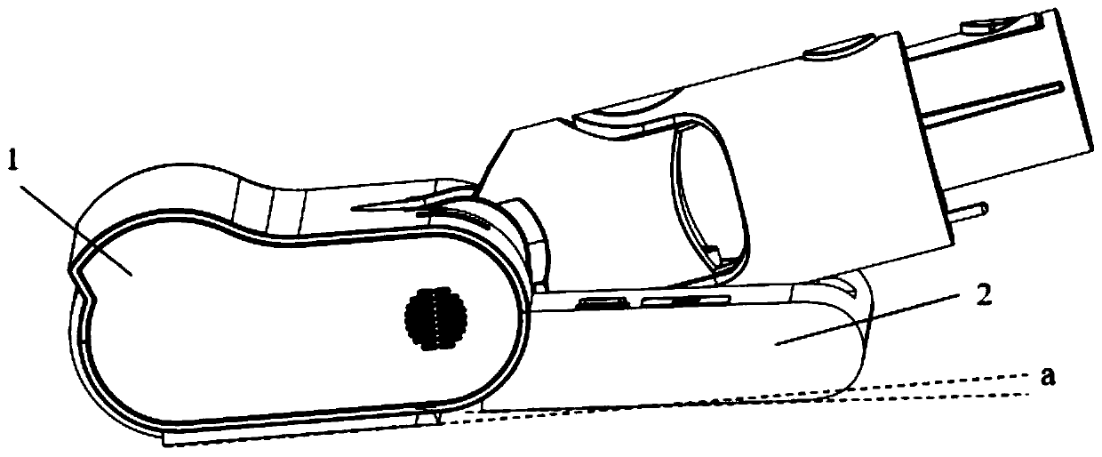
Technical field [0001] The invention relates to a water tank and cleaning equipment, belonging to the technical field of cleaning tools. Background technique [0002] The prior art composite vacuum cleaner generally includes a floor brush and a flat mop. In order to allow the flat mop to automatically discharge water, the flat mop is provided with air intake holes that make the air pressure inside and outside the flat mop equal. However, the air intake holes of the general flat drag are directly arranged on the shell of the flat drag. After use, the air holes set on the flat drag are easy to be free-falling dust or particles after it is placed upside down according to the use position. After covering, it is blocked, and the ventilation function is lost. Summary of the invention [0003] The object of the present invention is to provide a water tank and a cleaning device, which can prevent dust from clogging the air inlet by arranging the exhaust assembly with the air inlet hole a...

Claims


Application Information

Patent Timeline
IPC IPC(8): A47L11/40A47L11/28
CPCA47L11/4083A47L11/28A47L11/4094
Inventor 冯勇兵尤全
Owner DREAM INNOVATION TECH (SUZHOU) CO LTD
Learn More