Motorcade driving method based on roadside equipment

A technology of roadside equipment and driving method, which is applied to the traffic control system, arrangement situation, instruments and other directions of road vehicles, and can solve the problem that the first vehicle cannot transmit the information to the rear vehicle, the first vehicle following the vehicle has a low degree of control, and the rear Vehicles cannot avoid problems such as automatic avoidance, so as to achieve the effect of improving automatic driving ability, high sensitivity, and timely avoidance of failures

Pending Publication Date: 2020-06-09
TONGJI UNIV
View PDF15 Cites 14 Cited by
  • Summary
  • Abstract
  • Description
  • Claims
  • Application Information

AI Technical Summary

Problems solved by technology

[0006] All the following vehicles in the fleet rely on their own positioning unit to obtain position information and send their own position information to the next and adjacent vehicle, which requires that the position information of each vehicle must be high-precision, and each vehicle The car can only drive along the center line of the lane. If there is an obstacle on the lane, even if the first car can detect and avoid it in time, the first car cannot transmit this information to the rear vehicle, and the rear vehicle cannot automatically avoid it, causing the first car to follow. The control degree of the vehicle is not high, and the road surface required by the entire fleet is very demanding; at the same time, each vehicle obtains position information according to its own positioning unit and transmits it to the rear, which requires each vehicle in the fleet to have high-precision communication And positioning function, once the position information accuracy of any vehicle in the middle of the fleet is low and the position information is out of sync, it will cause a chain effect, that is, the vehicles behind the car in the fleet deviate from the normal driving route, and the failure rate of the fleet is high.

Method used


Image

  • Motorcade driving method based on roadside equipment
  • Motorcade driving method based on roadside equipment
  • Motorcade driving method based on roadside equipment

Examples


Embodiment Construction

[0046] The present invention will be described in detail below in conjunction with the accompanying drawings and specific embodiments. This embodiment is carried out on the premise of the technical solution of the present invention, and detailed implementation and specific operation process are given, but the protection scope of the present invention is not limited to the following embodiments.

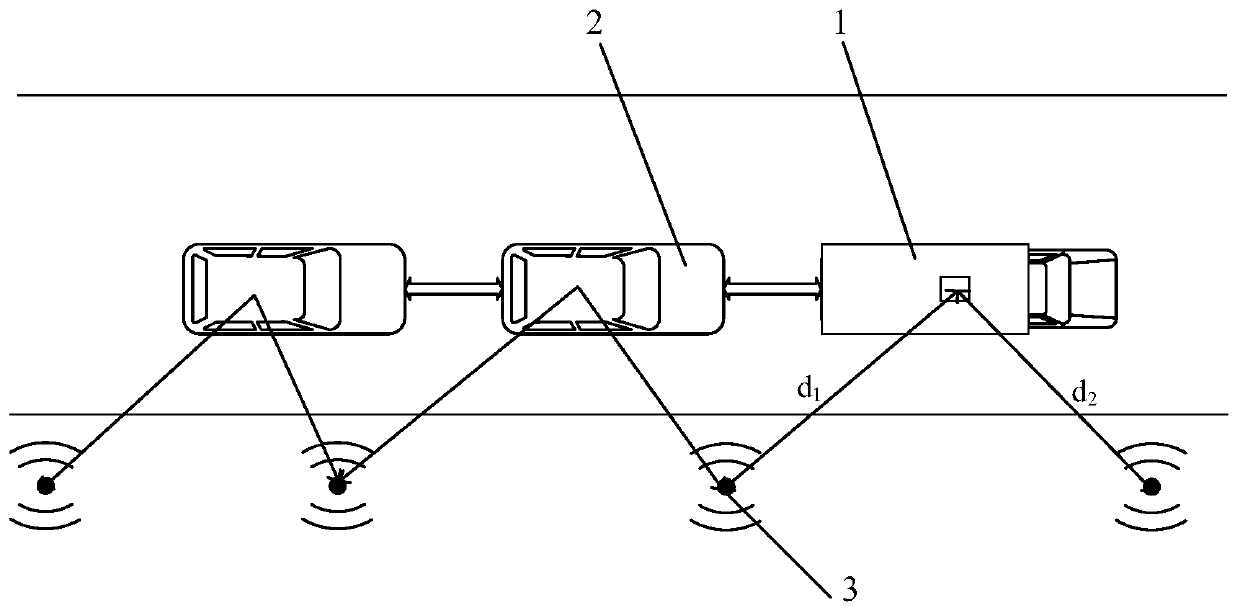
[0047] A fleet driving method based on roadside equipment, such as figure 1 shown, including:

[0048] The roadside device 3 is set on the roadside for real-time collection of high-precision map information. The roadside device 3 also stores its own position coordinates and serial numbers. Multiple follower vehicles 2 follow a lead vehicle 1 and drive side by side to form a fleet. Follower car 2 is a low-level self-driving vehicle equipped with an ACC system, the ACC system includes a radar detector, and the lead car 1 is a high-level self-driving vehicle;

[0049] Each vehicle in t...


PUM


Abstract

The invention relates to a motorcade driving method based on roadside equipment. The method comprises steps of enabling the roadside equipment to be disposed at a roadside, enabling at least one following vehicle to follow one pilot vehicle, forming a motorcade, enabling the following vehicle to be a low-grade automatic driving vehicle, and enabling the pilot vehicle to be a high-grade automatic driving vehicle; enabling the pilot vehicle receive the high-precision map information sent by roadside devices and carry out planning driving, enabling each vehicle in the motorcade establish communication with at least two roadside devices and periodically obtain position coordinates of the vehicle based on a signal propagation power loss model, and forming a driving track of the vehicle; enabling each vehicle share the driving track with an adjacent following vehicle behind through wireless communication, and enabling each following vehicle drive along the driving track of a previous vehicle. Compared with the prior art, the method has advantages of high safety, high sensitivity, high error-tolerant rate and the like.

Description

technical field [0001] The invention relates to automatic driving technology, in particular to a roadside equipment-based fleet driving method. Background technique [0002] Since the 21st century, the rapid development of computer technology has brought revolutionary changes to the automobile manufacturing industry. Automobile intelligence has become the general trend of the current automobile manufacturing industry, and autonomous driving is the focus and hotspot of current research on automobile intelligence. [0003] The U.S. National Highway Traffic Safety Administration (NHTSA) and the Society of Motor Engineers (SAE) divide the level of automatic driving into six levels, L0-L5, but most of the cars with automatic driving functions in my country are still in the lower level of L1. , L2 level, due to the hardware and software limitations of the vehicle itself, it is impossible to achieve high-level automatic driving functions. However, low-level autonomous driving is st...

Claims


Application Information

Patent Timeline
Patent Type & Authority Applications(China)
IPC IPC(8): G08G1/00G08G1/0967
CPCG08G1/096725G08G1/096783G08G1/20G08G1/22
Inventor 肖骁胡笳
Owner TONGJI UNIV
Why Eureka
Try Eureka