Laminated tube-in-tube evaporator
An evaporator and casing-type technology, which is applied in the field of stacked casing-type evaporators, can solve the problems of the heat transfer efficiency reduction of the refrigeration system and the reduction of the effective volume of the refrigerant cycle, etc., and achieve extended refrigeration time, fast equilibrium speed, and improved The effect of heat transfer efficiency
- Summary
- Abstract
- Description
- Claims
- Application Information
AI Technical Summary
Problems solved by technology
Method used
Image
Examples
Embodiment 1
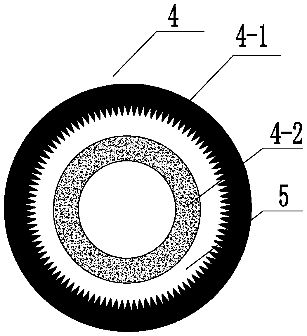
[0034] see Figure 1-7 As shown, the present invention is a stacked casing type evaporator, including an evaporator 4; the outside of the evaporator 4 is an outer sleeve 4-1; an inner liner 4-2 is installed inside the outer sleeve 4-1;
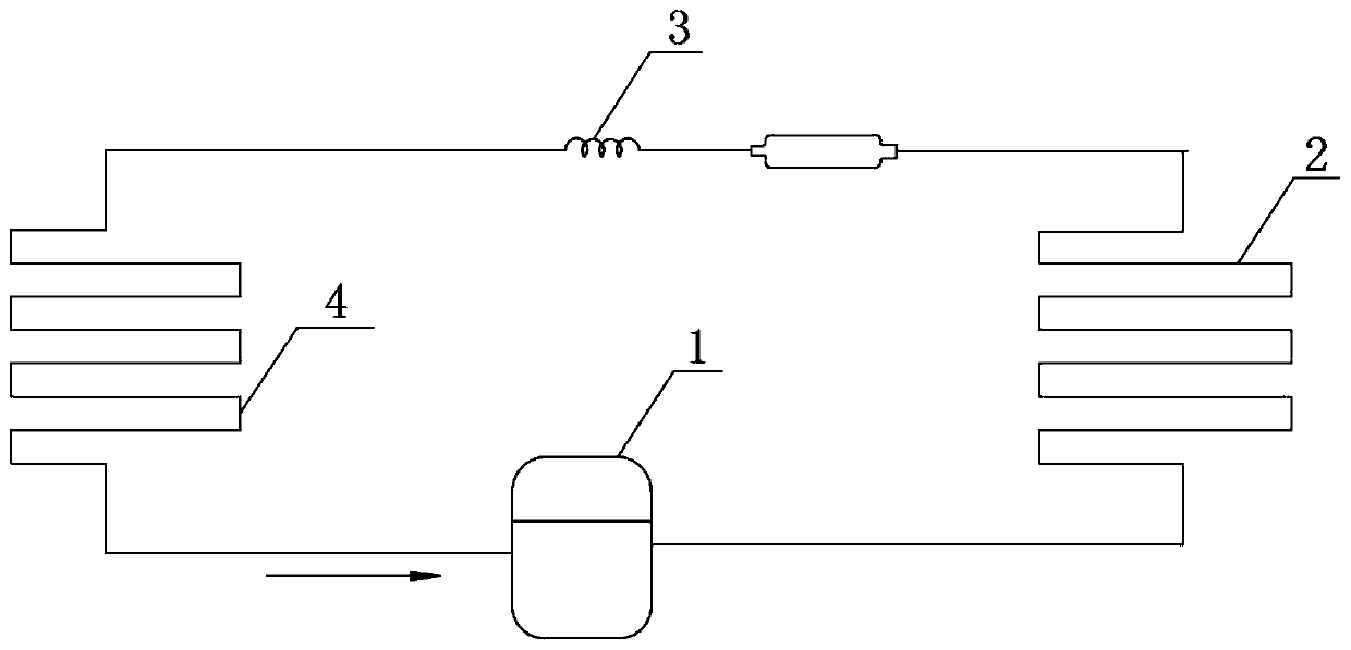
[0035] Among them, such as Figure 1-2 As shown, the outlet of the evaporator 4 is sequentially connected with a compressor 1, a condenser 2 and a throttling device 3; the outlet of the throttling device 3 is connected with the inlet of the evaporator 4 to form a circulating refrigeration system; the interior of the circulating refrigeration system is filled with Refrigerant 5; refrigerant 5 flows out from the outlet of compressor 1, and flows through condenser 2, throttling device 3 and evaporator 4 in sequence, and finally flows into the inlet of compressor 1; the inner liner 4-2 is arranged on the outer casing 4-1 entry end.
[0036] preferred, such as figure 1 , 3 As shown in and 4, the inner surface of the outer sleeve 4-1 is an uneve...
Embodiment 2
[0042] see Figure 1-7 As shown, the present invention is a stacked casing type evaporator, including an evaporator 4; the outside of the evaporator 4 is an outer sleeve 4-1; an inner liner 4-2 is installed inside the outer sleeve 4-1;
[0043] Among them, such as Figure 1-2 As shown, the outlet of the evaporator 4 is sequentially connected with a compressor 1, a condenser 2 and a throttling device 3; the outlet of the throttling device 3 is connected with the inlet of the evaporator 4 to form a circulating refrigeration system; the interior of the circulating refrigeration system is filled with Refrigerant 5; refrigerant 5 flows out from the outlet of compressor 1, and flows through condenser 2, throttling device 3 and evaporator 4 in sequence, and finally flows into the inlet of compressor 1; the inner liner 4-2 is arranged on the outer casing 4-1 entry end.
[0044] preferred, such as figure 1 , 3 As shown in and 4, the inner surface of the outer sleeve 4-1 is an uneve...
Embodiment 3
[0049] see Figure 1-7 As shown, the present invention is a stacked casing type evaporator, including an evaporator 4; the outside of the evaporator 4 is an outer sleeve 4-1; an inner liner 4-2 is installed inside the outer sleeve 4-1;
[0050] Among them, such as Figure 1-2 As shown, the outlet of the evaporator 4 is sequentially connected with a compressor 1, a condenser 2 and a throttling device 3; the outlet of the throttling device 3 is connected with the inlet of the evaporator 4 to form a circulating refrigeration system; the interior of the circulating refrigeration system is filled with Refrigerant 5; refrigerant 5 flows out from the outlet of compressor 1, and flows through condenser 2, throttling device 3 and evaporator 4 in sequence, and finally flows into the inlet of compressor 1; the inner liner 4-2 is arranged on the outer casing 4-1 entry end.
[0051] preferred, such as Figure 7 As shown, there are V-shaped grooves 4-3 in a circumferential array on the i...
PUM
 Abstract
Description
Claims
Application Information
 - Generate Ideas
- Intellectual Property
- Life Sciences
- Materials
- Tech Scout
- Unparalleled Data Quality
- Higher Quality Content
- 60% Fewer Hallucinations
Browse by: Latest US Patents, China's latest patents, Technical Efficacy Thesaurus, Application Domain, Technology Topic, Popular Technical Reports.
© 2025 PatSnap. All rights reserved.Legal|Privacy policy|Modern Slavery Act Transparency Statement|Sitemap|About US| Contact US: help@patsnap.com


