Steel wheel and flexible wheel integrated structure driven by speed reducer for robot

A reducer and robot technology, applied in the direction of transmission, transmission parts, mechanical equipment, etc., can solve the problems of affecting the clarity of the oil display screen, shortening the service life of the reducer, and prone to scratches on the surface, so as to achieve integration Good operation and heat dissipation, avoid severe vibration, and excellent running effect

Inactive Publication Date: 2020-06-09
嘉兴中商红船文化传媒有限公司
View PDF0 Cites 0 Cited by
  • Summary
  • Abstract
  • Description
  • Claims
  • Application Information

AI Technical Summary

Problems solved by technology

[0002] The reducer is generally used for low-speed and high-torque transmission equipment. The motor, internal combustion engine or other high-speed running power is used to achieve the purpose of deceleration through the gear with a small number of teeth on the input shaft of the reducer and the large gear on the output shaft. Ordinary The reducer will also have several pairs of gears with the same principle to achieve the ideal deceleration effect. The ratio of the number of teeth of the large and small gears is the transmission ratio. This transmission method can achieve the deceleration effect, but the deceleration is through the card between the large gear and the small gear. Combined rotation will inevitably generate heat. At the same time, it will generate huge noise when rotating, which will greatly shorten the service life of the reducer and lead to unstable performance.
[0003] There are certain disadvantages in the use of the existing reducer for robots. First, after a long-term use of the oil quantity display, the surface is prone to scratches, which affects the clarity of the oil quantity display and makes it difficult for people to view the data. Secondly, There is no device that integrates the steel wheel and the flexible wheel, and the rotation rate cannot be easily changed. Long-term use will lead to performance degradation. At the same time, the heat dissipation effect is not very ideal, which has brought certain influence during the use process. For this reason, We propose a steel-wheel-flexible-wheel-integrated structure driven by a reducer for a robot

Method used


Image

  • Steel wheel and flexible wheel integrated structure driven by speed reducer for robot
  • Steel wheel and flexible wheel integrated structure driven by speed reducer for robot
  • Steel wheel and flexible wheel integrated structure driven by speed reducer for robot

Examples


Embodiment Construction

[0016] In order to make the technical means, creative features, goals and effects achieved by the present invention easy to understand, the present invention will be further described below in conjunction with specific embodiments.

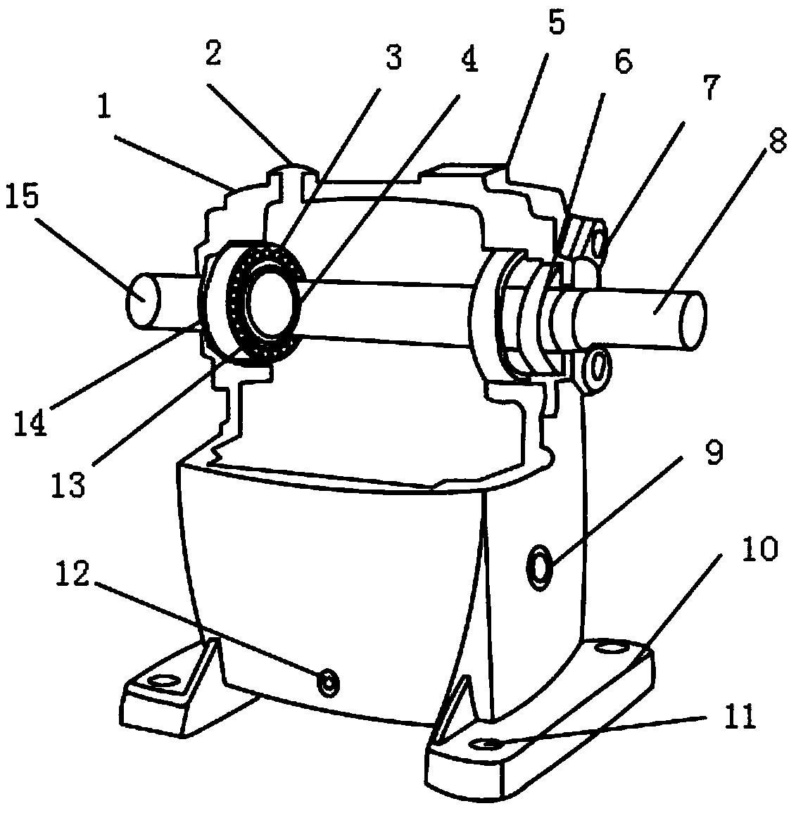
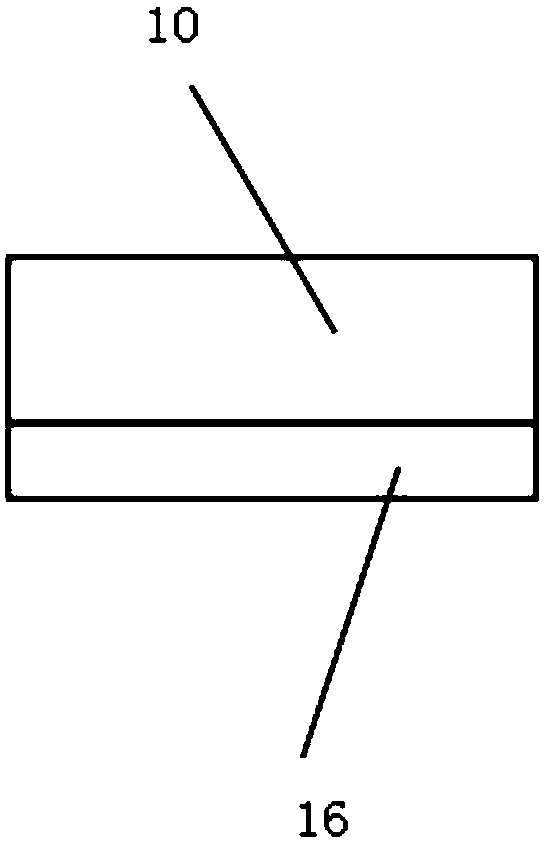
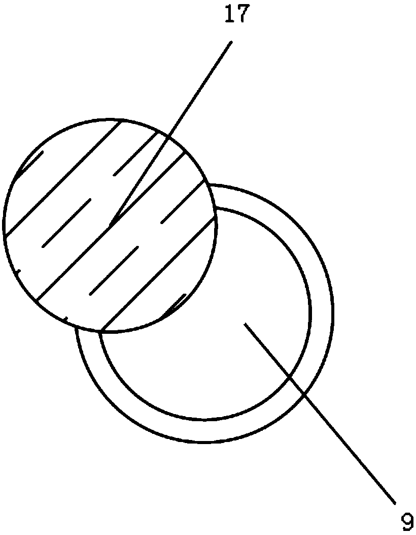
[0017] Such as Figure 1-3 As shown, a steel wheel and flexible spline integrated structure driven by a reducer for a robot includes a box body 1, an oil quantity display screen 9 and a steel wheel 14. The lower end of the box body 1 is provided with a base 10, and the base 10 An installation hole 11 is fixedly installed inside, a shock-absorbing layer 16 is provided at the lower end of the base 10, a radiator 5 is provided at the upper end of the box body 1, and an oil delivery port 2 is provided at one side of the radiator 5, so that The inside of the casing 1 is provided with an output shaft 8, and the outer surface of the output shaft 8 is provided with an oil seal 6, one side of the casing 1 is provided with an end cover 7, and one side of th...


PUM


Abstract

The invention discloses a steel wheel and flexible wheel integrated structure driven by a speed reducer for a robot. The steel wheel and flexible wheel integrated structure comprises a box body, an oil quantity display screen and a steel wheel, wherein a machine base is arranged at the lower end of the box body; a damping layer is arranged at the lower end of the machine base; a radiator is arranged at the upper end of the box body; an output shaft is arranged inside the box body; an input shaft is arranged on one side of the output shaft; a wave generation assembly is arranged on the outer surface of the input shaft; and a flexible wheel is arranged on the outer surface of the wave generation assembly. According to the steel wheel and flexible wheel integrated structure driven by the speed reducer for the robot, an anti-scratch film, the wave generation assembly and the radiator are arranged, so that scratches can be prevented from being generated on the surface of the oil quantity display screen after the oil quantity display screen is used for a long time, the definition of the oil quantity display screen is protected, the steel wheel and the flexible wheel can be integrated, the rotating speed can be easily changed, meanwhile, the heat dissipation effect is excellent, the damage caused by too high internal temperature is avoided, the steel wheel and flexible wheel integrated structure is suitable for different working conditions, and better application prospects are brought.

Description

technical field [0001] The invention relates to the field of robot reducers, in particular to an integrated structure of a steel wheel and a flexible spline driven by a reducer for a robot. Background technique [0002] The reducer is generally used for low-speed and high-torque transmission equipment. The motor, internal combustion engine or other high-speed running power is used to achieve the purpose of deceleration through the gear with a small number of teeth on the input shaft of the reducer and the large gear on the output shaft. Ordinary The reducer will also have several pairs of gears with the same principle to achieve the ideal deceleration effect. The ratio of the number of teeth of the large and small gears is the transmission ratio. This transmission method can achieve the deceleration effect, but the deceleration is through the card between the large gear and the small gear. It will inevitably generate heat, and at the same time, it will generate huge noise wh...

Claims


Application Information

Patent Timeline
IPC IPC(8): F16H49/00F16H55/17F16H57/028F16H57/04
CPCF16H49/00F16H55/17F16H57/028F16H57/0417F16H57/0449
Inventor 许明
Owner 嘉兴中商红船文化传媒有限公司
Why Eureka
Try Eureka