Plate cutting device

A cutting device and board technology, applied in wood processing equipment, special forming/shaping machines, manufacturing tools, etc., can solve the problems of requiring a lot of manpower, being easily injured, and low processing efficiency, so as to ensure personal safety, convenient operation, The effect of simple structure

Inactive Publication Date: 2020-06-09
宁波市萨哈机械科技有限公司
View PDF0 Cites 6 Cited by
  • Summary
  • Abstract
  • Description
  • Claims
  • Application Information

AI Technical Summary

Problems solved by technology

[0002] The board is a flat rectangular building material board made into a standard size. It is used in the construction industry. The board has a large surface area, so it has a strong ability to contain and cover. It is widely used in chemical industry, containers, construction, metal products, metal structures, etc., and the board can be used It can be cut, bent, stamped, welded, and made into various product components at will. It is flexible and convenient to use. It occupies an extremely important position in the departments of automobile, aviation, shipbuilding and tractor manufacturing. When the plate needs to be cut into a circular plate, most of the workers do it manually Cutting, which will be affected by the worker's technology and state, and the processing efficiency is low, requiring a lot of manpower, and it is easy to be injured during processing

Method used


Image

  • Plate cutting device
  • Plate cutting device
  • Plate cutting device

Examples


Embodiment Construction

[0017] All features disclosed in this specification, or steps in all methods or processes disclosed, may be combined in any manner, except for mutually exclusive features and / or steps.

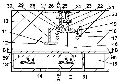
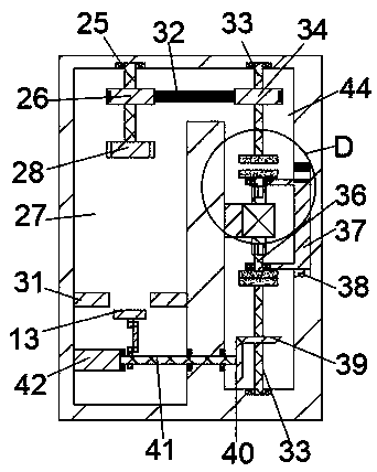
[0018] Combine below Figure 1-6 The present invention is described in detail, and for convenience of description, the orientations mentioned below are now stipulated as follows: figure 1 The up, down, left, right, front and back directions of the projection relationship itself are the same.

[0019] A plate cutting device of the device of the present invention includes a cutting machine 10, a cutting chamber 27 is arranged in the cutting machine 10, and the lower side of the cutting chamber 27 is communicated with left and right sides through a feed port 59 and a discharge port 60. A sliding cavity 16 communicating with the outside world, the lower side of the sliding cavity 16 is connected with a transmission cavity 14, and the transmission cavity 14 is provided with a transmission plate 13...


PUM


Abstract

The invention discloses a plate cutting device. The device comprises a cutting machine, wherein a cutting cavity is arranged in the cutting machine, a lower side of the cutting cavity is communicatedwith a sliding cavity, the left side and the right side of the sliding cavity are communicated with the outside through a feed port and a discharge port, the lower side of the sliding cavity is communicated with a conveying cavity, the conveying cavity is internally provided with a conveying plate, the lower end of the conveying plate is fixed by two conveying assemblies which are the same on theleft and the right sides, a front end wall and a rear end wall of the lower side of the sliding cavity are respectively and fixedly provided with a sliding platform, the right side of the conveying cavity is provided with a blanking cavity communicated with the sliding cavity, a through hole matched with the blanking cavity is formed in the sliding platform, a supporting shaft is rotatably arranged on the upper end wall of the cutting cavity, the lower end of the supporting shaft is connected with a first spline shaft through a first spline sleeve, and a round disc is fixedly arranged at the lower end of a first reciprocating shaft. A motor drives a cutting knife to cut the plate by rotating a circle, and a pressing block presses the plate to prevent the plate from moving to influence thecutting, the manual cutting is not needed, and labor is saved.

Description

technical field [0001] The invention relates to the technical field of plates, in particular to a plate cutting device. Background technique [0002] The board is a flat rectangular building material board made into a standard size. It is used in the construction industry. The board has a large surface area, so it has a strong ability to contain and cover. It is widely used in chemical industry, containers, construction, metal products, metal structures, etc., and the board can be used It can be cut, bent, stamped, welded, and made into various product components at will. It is flexible and convenient to use. It occupies an extremely important position in the departments of automobile, aviation, shipbuilding and tractor manufacturing. When the plate needs to be cut into a circular plate, most of the workers do it manually Cutting, which will be affected by the worker's technology and state, and the processing efficiency is low, requiring a lot of manpower, and it is easy to ...

Claims


Application Information

Patent Timeline
IPC IPC(8): B27C5/02B27C5/06
CPCB27C5/02B27C5/06
Inventor 王涛
Owner 宁波市萨哈机械科技有限公司
Why Eureka
Try Eureka