
Rotary-table fixture

A tooling fixture and turntable technology, which is applied in the field of tooling and fixtures, can solve the problems of losing the wide application of turntable fixtures and the inactivity of the fixtures, and achieves the effect of saving rotating force and reducing operating procedures.

Inactive Publication Date: 2020-06-09
温州潭兴精密机械有限公司
View PDF5 Cites 2 Cited by
  • Summary
  • Abstract
  • Description
  • Claims
  • Application Information

AI Technical Summary

Problems solved by technology

The clamping of the turntable fixture is the basis to ensure the high-precision machining of the workpiece. Usually, the fixed fixture is used to fix the workpiece, but at the same time, the universality of the turntable fixture is lost.

Method used


Image

  • Rotary-table fixture
  • Rotary-table fixture
  • Rotary-table fixture

Examples


Embodiment Construction

[0023] In the following, the present invention will be specifically described through exemplary embodiments. It should be understood, however, that elements, structures and characteristics of one embodiment may be beneficially incorporated in other embodiments without further recitation.

[0024] The turntable tooling fixture of the present invention is suitable for automatic processing equipment, robot equipment, etc., and the turntable tooling fixture provided by the present invention is described in detail below:

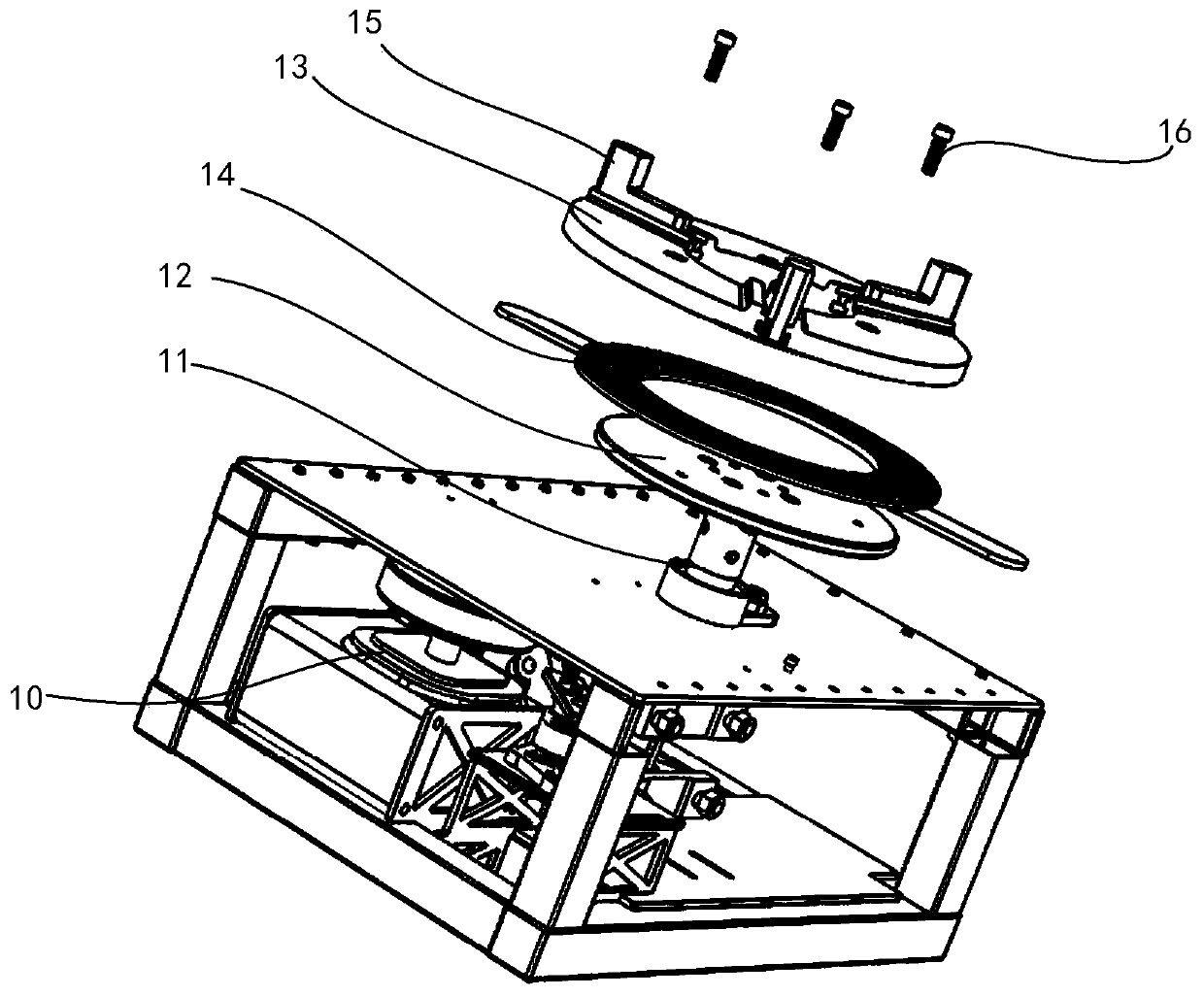
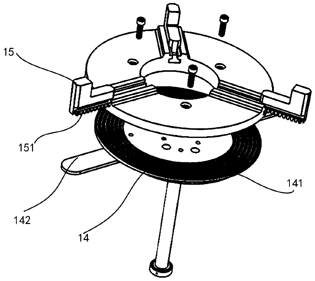
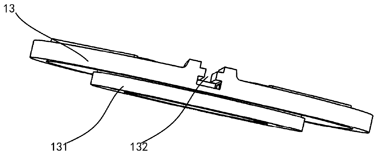
[0025] Figure 1-Figure 3 Shown is a schematic structural diagram of the turntable tooling fixture, which includes:

[0026] The driving motor 10 transmits its driving force to the rotating drive shaft 11, wherein the power of the driving motor 10 can also be transmitted through a belt.

[0027] The first turntable 12 is fixedly connected to the rotary drive shaft 11 and can rotate together with the rotary drive shaft 11. The first turntable 12 plays the role o...


PUM


Abstract

The invention provides a rotary-table fixture. The rotary-table fixture comprises a drive motor, a first rotary disc, a second rotary disc, a clamping element and an adjustment disc, wherein a drive force of the drive motor is transmitted to a rotary drive shaft; the first rotary disc is fixedly connected to the rotary drive shaft, and capable of rotating together with the rotary drive shaft; thesecond rotary disc is provided with a boss surface which penetrates through a workpiece placement hole and is formed in the depth direction of the workpiece placement hole, the boss surface faces thefirst rotary disc, and an adjustment guide rail is arranged on the surface of the second rotary disc in the radial direction; the clamping element is capable of moving in the adjustment guide rail, and adjustment teeth are arranged at the bottom of the clamping element; the adjustment disc is in the shape of a ring with an inner ring which is holes, and the adjustment disc is arranged between thefirst rotary disc and the second rotary disc; a tooth groove is formed in one surface facing the second rotary disc, of the adjustment disc, and the tooth groove is formed in the surface of the adjustment disc in the shape of an annular groove; and after the adjustment teeth are matched with the tooth groove, mutual fixing for the clamping element and the adjustment disc can be realized.

Description

technical field [0001] The invention belongs to the technical field of tooling fixtures, in particular to a turntable tooling fixture. Background technique [0002] During the automatic processing of the production line, the fixture is used in the production process to clamp the workpiece to fix the displacement and drop of the workpiece due to external force during the processing, resulting in the stop of processing or the processing There is a problem with the product that does not meet the standard. [0003] In the related art, the turntable fixture is widely used in the field of robotic automatic processing. During work, the turntable is rotated while the processing tool is not moving to realize the rotary processing of the workpiece, especially in the field of lathe turning. The clamping of the turntable fixture is the basis to ensure the high-precision machining of the workpiece. Usually, the fixation of the workpiece is realized by the way that the fixture is not mov...

Claims


Application Information

Patent Timeline
Patent Type & Authority Applications(China)
IPC IPC(8): B23B31/10B23B31/103B23B31/16
CPCB23B31/102B23B31/103B23B31/16B23B31/16083
Inventor 施国锋邵志达朱振旗
Owner 温州潭兴精密机械有限公司
Learn More