
Transfer method of micro light emitting diode and transfer substrate

A technology of light emitting diode and transfer method, applied in the field of micro light emitting diode, can solve the problems of residue, MicroLED open circuit, poor control of adhesive adhesion, etc., and achieve the effect of high transfer success rate

Inactive Publication Date: 2020-06-05
NANJING CEC PANDA LCD TECH
View PDF7 Cites 8 Cited by
  • Summary
  • Abstract
  • Description
  • Claims
  • Application Information

AI Technical Summary

Problems solved by technology

[0004] The traditional mass transfer generally uses adhesive glue tips to absorb and transfer Micro LEDs. During the process of Micro LEDs being transferred to the display backplane, after the Micro LEDs are transferred to the display backplane, in the process of lifting the tips Due to the poor control of the adhesiveness of the glue, it is easy to leave the glue on the tip on the Micro LED, resulting in an open circuit of the Micro LED in the subsequent process.

Method used


Image

  • Transfer method of micro light emitting diode and transfer substrate
  • Transfer method of micro light emitting diode and transfer substrate
  • Transfer method of micro light emitting diode and transfer substrate

Examples


Embodiment Construction

[0033] In order to more clearly illustrate the embodiments of the present invention or the technical solutions in the prior art, the specific implementation manners of the present invention will be described below with reference to the accompanying drawings. Obviously, the accompanying drawings in the following description are only some embodiments of the present invention, and those skilled in the art can obtain other accompanying drawings based on these drawings and obtain other implementations.

[0034] In order to make the drawing concise, each drawing only schematically shows the parts related to the present invention, and they do not represent the actual structure of the product. In addition, to make the drawings concise and easy to understand, in some drawings, only one of the components having the same structure or function is schematically shown, or only one of them is marked. Herein, "a" not only means "only one", but also means "more than one".

[0035] The techni...


PUM


Abstract

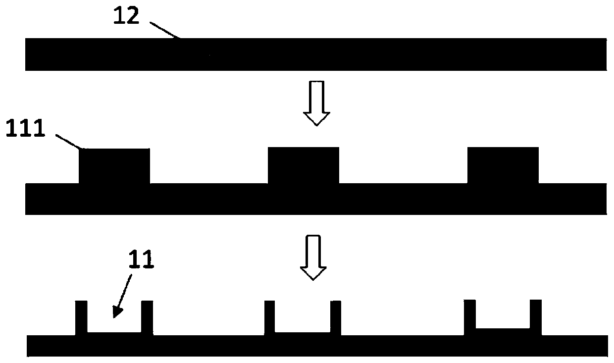
The invention provides a transfer method of a micro light-emitting diode and a transfer substrate, and relates to the field of micro light-emitting diodes. The method comprises the following steps ofS1, aligning and fitting the micro light emitting diodes on the transfer substrate with a convex groove and a transient substrate; S2, synchronously overturning the micro light-emitting diodes on thetransfer substrate and the transient substrate into an ultrasonic oscillation solution for ultrasonic oscillation, wherein the micro light-emitting diodes are oscillated to peel off the transient substrate; S3, moving away the transient substrate, taking out the transfer substrate, and drying the transfer substrate and the micro light emitting diodes in the grooves of the transfer substrate; S4, aligning and fitting the micro light emitting diodes on a display back plate and in the grooves of the transfer substrate, pressing the display back plate, and heating the transfer substrate to enablethe electrodes on the display back plate to be bonded with the bottom electrodes of the micro light-emitting diodes; and S5, separating the transfer substrate from the micro light emitting diode. According to the present invention, the micro light emitting diode is transferred through the transfer substrate with the groove structure, and the transfer success rate is improved.

Description

technical field [0001] The invention belongs to the field of miniature light-emitting diodes, and in particular relates to a transfer method of the miniature light-emitting diodes. [0002] technical background [0003] As a new generation of display technology, micro-device (Micro LED) is one of the most important challenges facing, how to implant a huge amount of Micro LED devices on the target substrate or circuit to reduce its manufacturing cost, and this link is called giant volume transfer. [0004] The traditional mass transfer generally uses adhesive glue tips to absorb and transfer Micro LEDs. During the process of Micro LEDs being transferred to the display backplane, after the Micro LEDs are transferred to the display backplane, in the process of lifting the tips Due to the poor control of the adhesiveness of the glue, it is easy to leave the glue on the tip on the Micro LED, resulting in an open circuit of the Micro LED in the subsequent process. Contents of th...

Claims


Application Information

Patent Timeline
Patent Type & Authority Applications(China)
IPC IPC(8): H01L21/677H01L21/683H01L27/15
CPCH01L21/67736H01L21/6835H01L27/156H01L2221/68368H01L2221/68381H01L2221/68386
Inventor 黄安朱景辉郁杰张良玉王俊星朱充沛
Owner NANJING CEC PANDA LCD TECH
Learn More