Method for removing floating slurry at pile head of cast-in-place pile

A cast-in-place pile and laitance technology, which is applied in sheet pile wall, construction, infrastructure engineering and other directions, can solve the problems of easily damaged pile head reinforcement, long concrete cycle, labor and material consumption, etc., and achieves good construction stability and short cycle. , the effect of simple structure

Active Publication Date: 2020-06-05
浙江宝盛建设集团有限公司
View PDF9 Cites 3 Cited by
  • Summary
  • Abstract
  • Description
  • Claims
  • Application Information

AI Technical Summary

Problems solved by technology

[0007] The invention mainly solves the deficiencies in the prior art of labor and material, easily damaged pile head steel bars and retained concrete, and a long period, and provides a method for removing pile head floating slurry of cast-in-place piles, which has the advantages of simple structure, time-saving and labor-saving , The advantages of good construction stability and short cycle

Method used


Image

  • Method for removing floating slurry at pile head of cast-in-place pile
  • Method for removing floating slurry at pile head of cast-in-place pile
  • Method for removing floating slurry at pile head of cast-in-place pile

Examples


Embodiment Construction

[0029] The technical solution of the invention will be further specifically described below through the embodiments and in conjunction with the accompanying drawings.

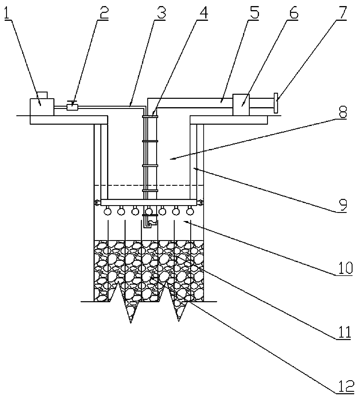
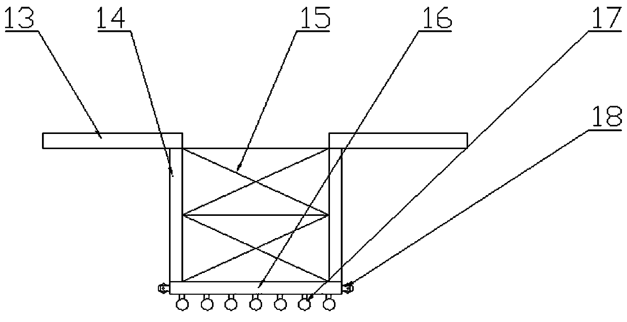
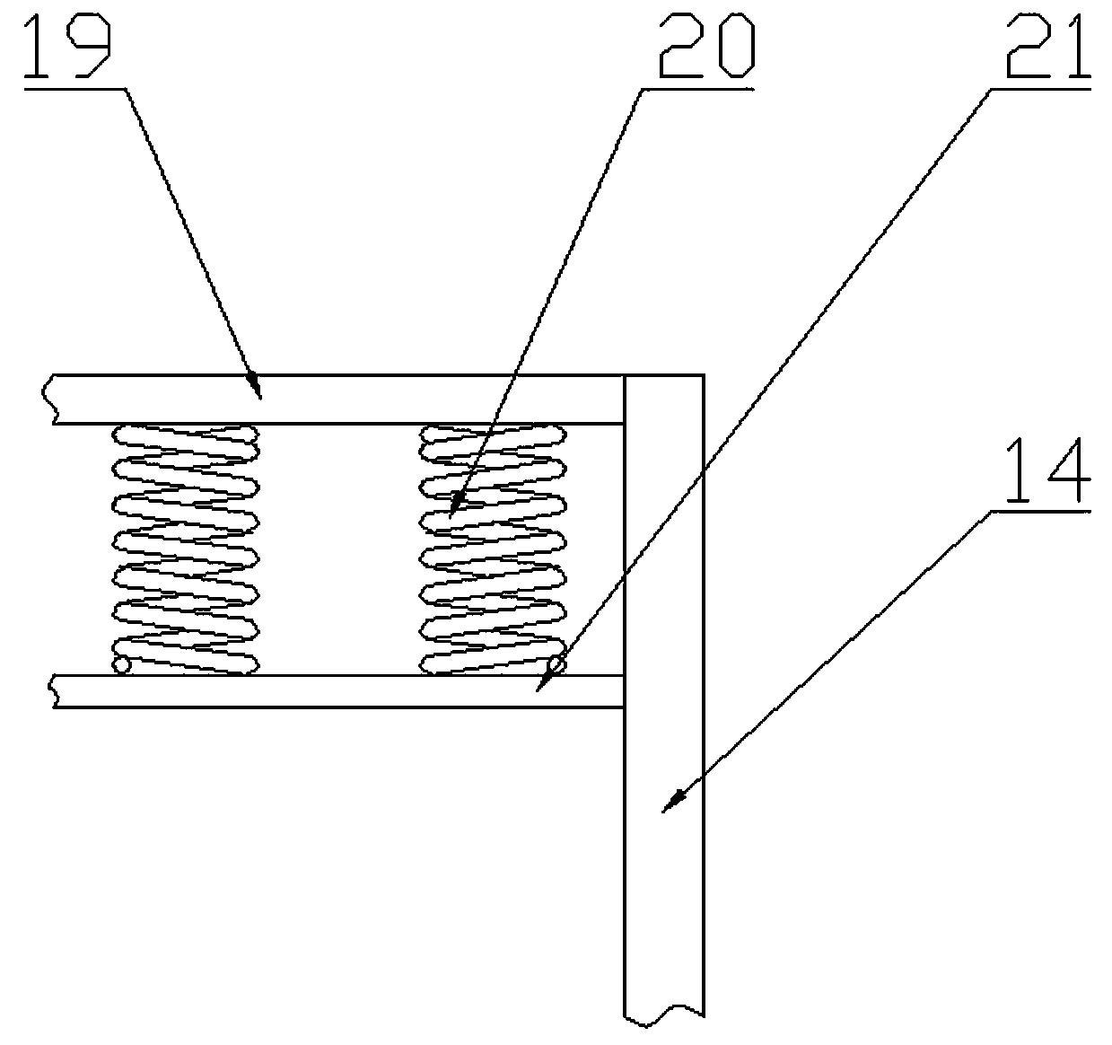
[0030] Embodiment: As shown in 1-4, a method for removing pile head laitance from cast-in-situ piles includes the following steps:

[0031] Step 1: Drill out the pile hole 8 first, then put the pile steel bar 11 into the pile hole 8, then pour concrete so that the middle and lower parts of the pile hole 8 are filled to form the pile body 12, and at the same time, the upper part of the pile hole 8 forms a layer of mud and concrete. Laitance 10.

[0032] The second step: then place the floating frame assembly 9 fixed with the slurry discharge pipe 5 and the high-pressure air supply pipe 3 into the pile hole 8 so that the lower ends of the slurry discharge pipe 5 and the high-pressure air supply pipe 3 are immersed in the floating slurry 10 . The high-pressure air supply pipe 3 is hooked into the lower port of th...


PUM


Abstract

The invention relates to a method for removing floating slurry at a pile head of a cast-in-place pile, and belongs to the technical field of cast-in-place pile construction. The method comprises the steps that firstly a pile hole is drilled, then a pile steel bar is placed into the pile hole, concrete is poured to the file hole to form a pile body, and meanwhile, mud and floating slurry of concrete are formed at the upper part of the pile hole; then a floating frame assembly fixedly provided with a slurry discharge pipe and a high-pressure gas supply pipe is placed into the pile hole, specifically, the lower ends of the slurry discharge pipe and the high-pressure gas supply pipe are immersed in the floating slurry; the floating frame assembly is suspended on the floating slurry through a plurality of floating balls at the lower end of a positioning underframe of the slurry discharge pipe until the floating frame assembly is in contact with the pile steel bar for induction limiting, andmeanwhile, the floating frame assembly is guided to move by a stable guide wheel assembly; and finally an air compressor, connected with the high-pressure gas supply pipe, on an equipment platform frame is started, and the fluid mud and the floating slurry are discharged to the ground via the slurry discharge pipe by high-pressure gas through the high-pressure gas supply pipe. The method has theadvantages of simple structure, time and labor saving, good construction stability and short period. It is ensured that only the slurry is blown out without taking out useful concrete aggregate.

Description

technical field [0001] The invention relates to the technical field of cast-in-situ pile construction, in particular to a method for removing floating slurry at pile heads of cast-in-situ piles. Background technique [0002] Cast-in-place pile is a kind of pile made by forming holes in place and pouring concrete or reinforced concrete. Commonly used are: [0003] (1) Drilled cast-in-place piles: use auger drilling rigs, submersible drilling rigs, etc. to pour concrete into holes on the spot to form piles. There is no vibration and no soil squeezing during construction, but the settlement of the piles is slightly larger. The auger drilling rig is suitable for cohesive soil, sandy soil and artificial filling soil above the groundwater level. The drilled soil block rises along the helical blade on the drill pipe and is discharged out of the hole. The hole diameter is about 300mm, and the drilling depth is 8-12m. Soil quality and water content to select drill pipe. The submer...

Claims


Application Information

Patent Timeline
Patent Type & Authority Applications(China)
IPC IPC(8): E02D13/08E02D5/34
CPCE02D5/34E02D13/08
Inventor 徐云茂马国珍
Owner 浙江宝盛建设集团有限公司
Why Eureka
Try Eureka