
Multipoint-discharging belt conveyor system

A belt conveying, multi-point technology, applied in the direction of conveyor objects, transportation and packaging, etc., can solve the problem of reducing the overlap height, etc., to achieve the effect of reducing the overlap height, reducing wear and tear, and saving construction investment

Pending Publication Date: 2020-06-05
COFCO ENG MAOSHENG EQUIP (HENAN) CO LTD +2
View PDF0 Cites 1 Cited by
  • Summary
  • Abstract
  • Description
  • Claims
  • Application Information

AI Technical Summary

Problems solved by technology

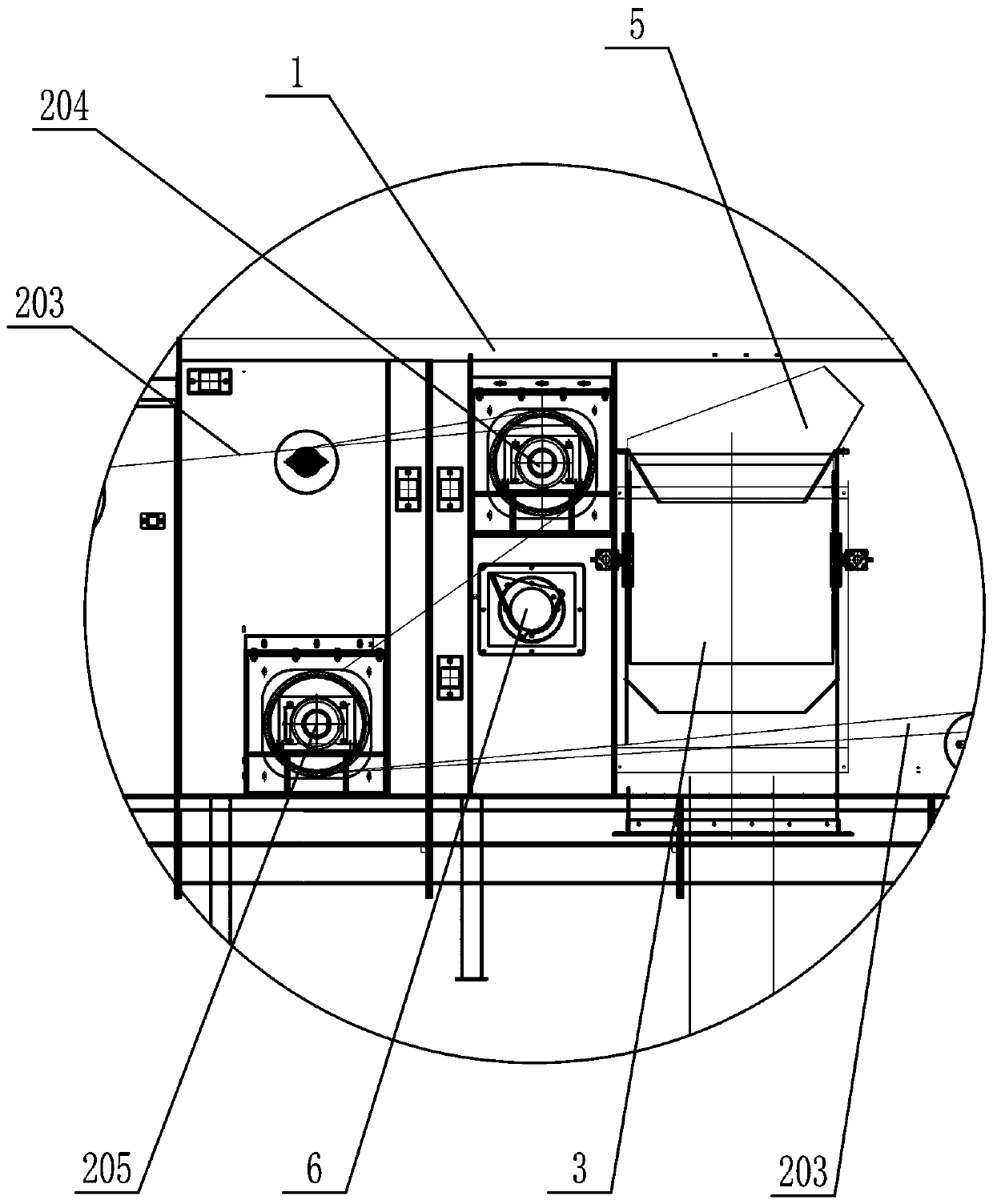
[0004] In summary, in order to overcome the deficiencies of the prior art problems, the invention provides a multi-point unloading belt conveyor system, which is to set a multi-point unloading belt conveyor in a closed casing. The unloading belt conveyor is equipped with multiple unloading points from the feeding end to the unloading end, and a four-way unloading device is installed at the unloading point, and the unloading at the unloading point is realized through the four-way unloading device Switching with throwing material, so as to realize the multi-point unloading of one conveyor. Conveyors are used in combination. When feeding materials in the silo close to the feeding inlet, you only need to start the corresponding multi-point unloading belt conveyor, and the subsequent conveyors do not need to be started. In the realization of multi-point unloading At the same time, it takes into account the energy waste of the conveyor, reduces the wear of the conveyor belt, and ensures the service life of the conveyor. The four-way unloading device at the lap joint can also effectively reduce the lap height of the equipment and save construction investment.

Method used


Image

  • Multipoint-discharging belt conveyor system
  • Multipoint-discharging belt conveyor system
  • Multipoint-discharging belt conveyor system

Examples


Embodiment 1

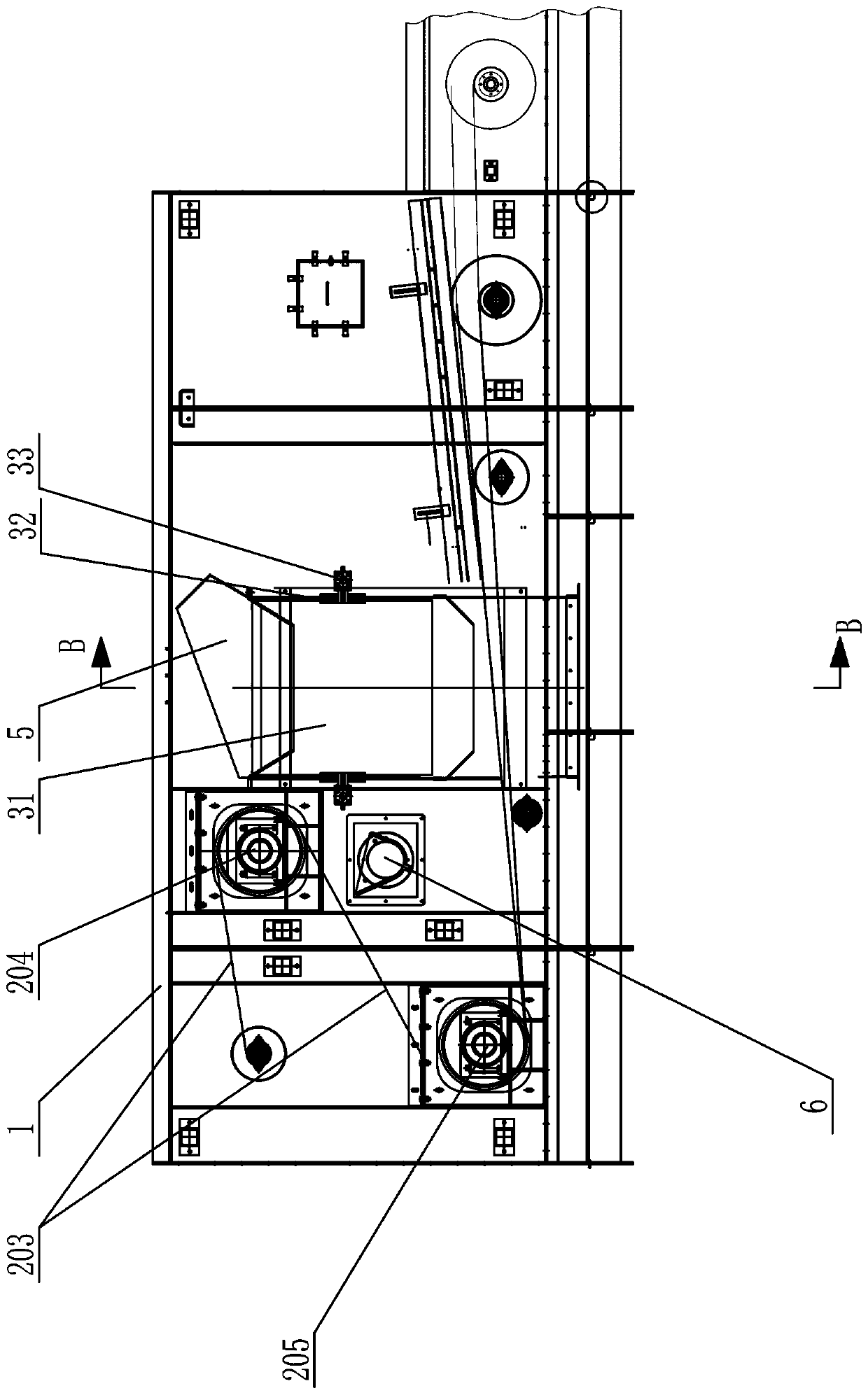
[0036] Such as Figure 1~9 As shown, a belt conveyor system for multi-point unloading includes a closed casing 1 and a multi-point unloading belt conveyor 2, the closed casing 1 is arranged above the silo, and the closed machine One end of the shell 1 is provided with a feeding inlet 4, and the closed casing 1 is provided with a multi-point unloading belt conveyor 2, and the multi-point unloading belt conveyor 2 includes a driven roller 201, a conveying Belt 203, multiple discharge points and drive roller 202, driven roller 201 is located at the feed end of multi-point discharge belt conveyor 2, drive roller 202 is located at the discharge end of multi-point discharge belt conveyor 2, A plurality of unloading points are arranged between the feed end and the unloading end, each unloading point is provided with a four-way unloading device 3, each unloading point is provided with a rising drum 204 and A falling roller 205, the driven roller 201, the rising roller 204, the fallin...

Embodiment 2

[0045] Such as Figure 10 and Figure 11 Shown, repeat embodiment one, have the following difference, the quantity of the multi-point unloading belt conveyor 2 in the closed casing 1 is many, and a plurality of multi-point unloaded belt conveyors 2 are in the closed casing 1 Connected in series, the feeding end of the next multi-point unloading belt conveyor 2 connected in series is set below the discharge end of the previous multi-point unloading belt conveyor 2, and each multi-point unloading belt conveyor 2 The unloading end and unloading point of each correspond to a silo, and the unloading end of the previous multi-point unloading belt conveyor 2 is connected to the latter multi-point unloading belt conveyor located below it through a four-way unloading device 3. The feeding end of the conveyor 2 and the feeding port of the silo.

[0046] In this embodiment, taking the feeding of seven silos as an example, three multi-point unloading belt conveyors 2 connected in series...


PUM


Abstract

The invention provides a multipoint-discharging belt conveyor system which comprises a sealed case and multipoint-discharging belt conveyors arranged in the sealed case. Multiple discharging points are arranged between the feeding ends and the discharging ends of the multipoint-discharging belt conveyors; a four-way discharging device is arranged on each discharging point; the switchover between discharging and throwing-conveying on each discharging point is realized through each four-way discharging device, so that multipoint discharging of the conveyors is realized; meanwhile, the multiple multipoint-discharging belt conveyors can be connected in series and combined for use, one four-way discharging device is arranged at the lap-joint part of each two multiple multipoint-discharging beltconveyors connected in series, and when materials are fed from a stock bin close to a feed inlet, only the corresponding multipoint-discharging belt conveyor needs to be started, and the follow-up conveyors have no need to be started, so that not only can multipoint discharging be realized, but also an energy waste problem is considered, the wear of a conveyor belt is reduced, and the service life of the conveyors is guaranteed; and the four-way discharging devices are arranged at the lap-joint parts, so that the equipment lap-joint height can be effectively reduced, and the building investment is saved.

Description

Technical field: [0001] The invention belongs to the technical field of grain conveying machinery and equipment, and in particular relates to a multi-point unloading belt conveying system. Background technique: [0002] At present, grain storage is usually realized by belt conveyors. With the continuous expansion of the scale of the grain depot, a grain depot is usually composed of multiple granaries. , the existing feed to the granary is usually multiple belt conveyors that are tilted and overlapped one by one to achieve multi-silo feeding. The overall height is very large after the overlap, and the pedestrian corridor needs to be made inclined, which is cumbersome, poor in safety, and inconvenient. , or use the scraper conveyor to realize the top feeding of the warehouse, the feeding is convenient but the power consumption is large, and the grain is easily broken. In order to solve the existing technical problems, the applicant has applied for a Chinese invention patent w...

Claims


Application Information

Patent Timeline
Patent Type & Authority Applications(China)
IPC IPC(8): B65G47/34
CPCB65G47/34
Inventor 任守华王凤成夏朝勇王中营张法行上官林波朱明俊郭永刚孙慧男
Owner COFCO ENG MAOSHENG EQUIP (HENAN) CO LTD
Learn More