Orthopedic joint

An orthopedic, joint technology, applied in medical science, prosthesis, artificial legs, etc., can solve problems such as noise formation, clipping clothes, frequent maintenance of stretching aids, etc., and achieve the effect of reducing wear and noise.

Pending Publication Date: 2020-06-02
OTTOBOCK SE & CO KGAA
View PDF9 Cites 2 Cited by
  • Summary
  • Abstract
  • Description
  • Claims
  • Application Information

AI Technical Summary

Problems solved by technology

[0007] Problems with prior art devices are that stretching aids require frequent maintenance, can catch clothing and are prone to wear and tear when soiled and are sometimes prone to noise

Method used


Image

  • Orthopedic joint
  • Orthopedic joint
  • Orthopedic joint

Examples


Embodiment Construction

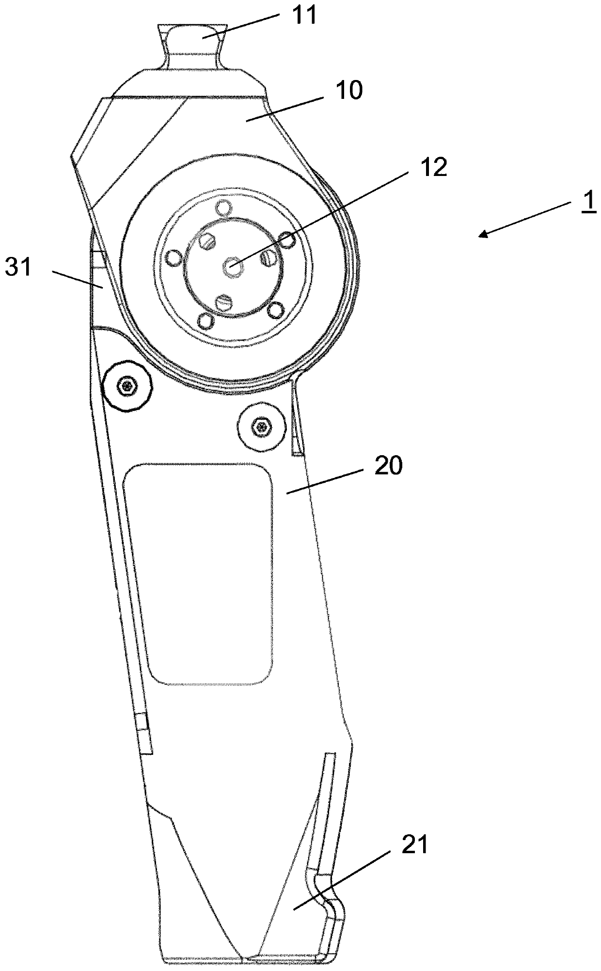
[0026] figure 1A side view of an orthopedic technical joint in the form of an external prosthetic knee joint 1 with an upper part 10 comprising an upper connection means 11 in the form of a pyramid adapter is shown in . A prosthesis cartridge for receiving the femur stump can be fastened to the upper connection element 11 . The upper part 10 is mounted pivotably about a pivot axis 12 about a lower part 20 , on the distal end of which a receptacle 21 for a lower leg tube is formed. A housing 31 is constructed or arranged within the lower part 20 , in which the rotary hydraulics are accommodated. Other components of the rotary hydraulics can be arranged in the lower part 20, which in combination with figure 2 elaborate.

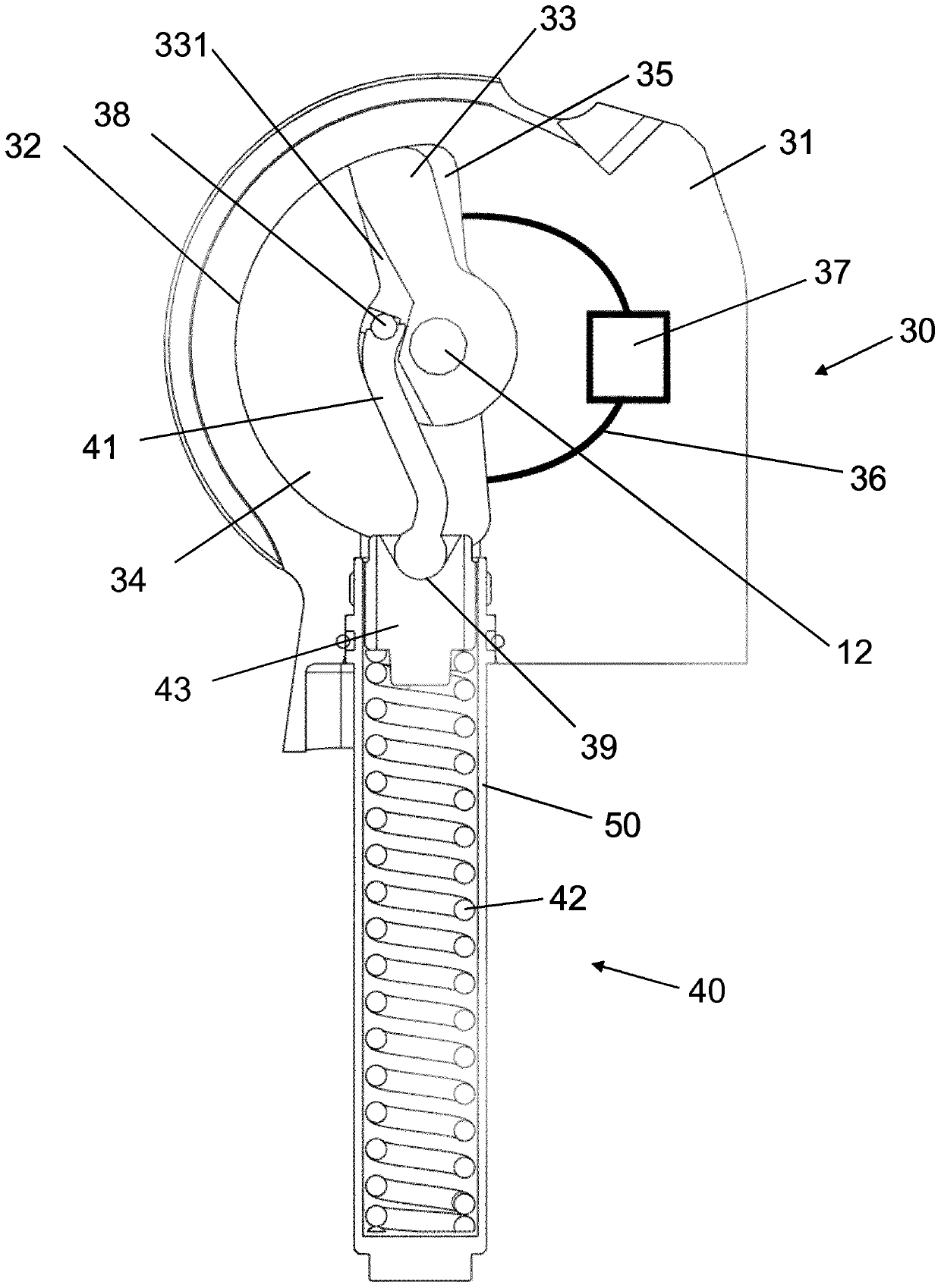
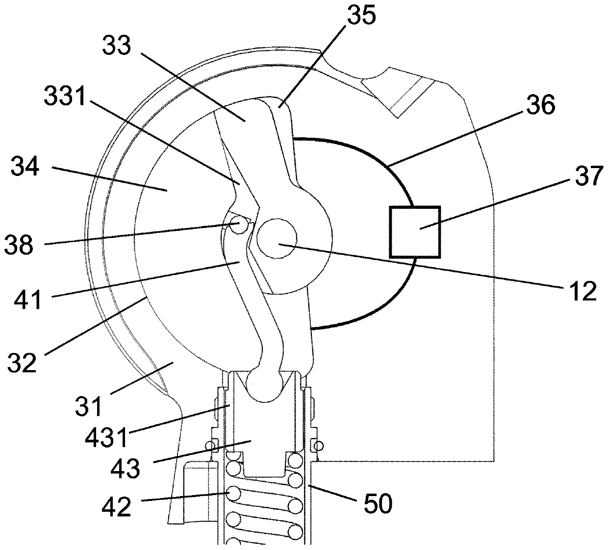
[0027] figure 2 The basis for having a housing 30 is shown in a cross-sectional view figure 1 Part of the prosthetic knee joint 1 , in which a chamber 32 is formed, in which chamber a pivot piston 33 is mounted pivotably about a pivot axis 12 . The pros...


PUM


Abstract

The invention relates to an orthopedic joint for a prosthesis, comprising an upper part (10), a lower part (20) which is mounted on the upper part in a pivotal manner about a pivot axis (12), and a rotation hydraulic unit (30), which has a housing (31) with a chamber (32) and a pivot piston (33) that is pivotally mounted in the chamber and divides the chamber (32) into a flexion chamber (34) and an extension chamber (35), said chambers being hydraulically connected together via at least one channel (36). The joint also comprises a pretensioning device (40) which supports a pivoting movement ofthe upper part (10) relative to the lower part (20), wherein the pretensioning device (40) is coupled directly to the pivot piston (33) via a support (41).

Description

technical field [0001] The invention relates to a technical orthopedic joint with an upper part, a lower part mounted on the upper part so as to be pivotable about a pivot axis, and a hydraulic swivel device with a swivel housing with a swivel housing. chamber and a oscillating piston swingably supported in the chamber, the oscillating piston divides the chamber into a flexion chamber and an extension chamber, the two chambers are hydraulically connected to each other via at least one channel, and the joint has a predetermined A tensioning device supports the swinging movement of the upper part relative to the lower part. Background technique [0002] Orthopedic joints for orthopedic devices, such as orthoses or external prostheses, serve to articulately connect the upper part to the lower part. A swivel axis is formed between the upper part and the lower part, which has a fixed assignment to the upper part and the lower part in a monocentric joint, and in a polycentric joi...

Claims


Application Information

Patent Timeline
Patent Type & Authority Applications(China)
IPC IPC(8): A61F2/64A61F2/68A61F2/50A61F2/74
CPCA61F2/64A61F2/68A61F2002/5073A61F2002/5087F15B15/12A61F5/0123F15B15/1476A61F2/744A61F2/748A61F2/74A61F2002/5006
Inventor H·博伊特
Owner OTTOBOCK SE & CO KGAA
Why Eureka
Try Eureka