Fan-shaped heat dissipation cable and fan-shaped heat dissipation optical cable

A fan-shaped and cable technology, which is applied in the direction of power cables, insulated cables, cables, etc., can solve the problems of reduced tear resistance, poor cable heat dissipation, and low efficiency, and achieve light weight, excellent heat dissipation, and tear resistance. strong effect

Inactive Publication Date: 2020-06-02
SUZHOU ZHUANCHUANG PHOTOELECTRIC TECH CO LTD
View PDF5 Cites 2 Cited by
  • Summary
  • Abstract
  • Description
  • Claims
  • Application Information

AI Technical Summary

Problems solved by technology

[0007] In the prior art, cables often use circular conductors and closed insulating layers. The heat dissipation effect of cables with this structure is poor. In addition, the use of continuous channels on the outer sheath greatly reduces the tear resistance; in the prior art The cable adopts a twisted structure, and the full section needs to be stripped, so the efficiency is low

Method used


Image

  • Fan-shaped heat dissipation cable and fan-shaped heat dissipation optical cable
  • Fan-shaped heat dissipation cable and fan-shaped heat dissipation optical cable
  • Fan-shaped heat dissipation cable and fan-shaped heat dissipation optical cable

Examples


Embodiment 1

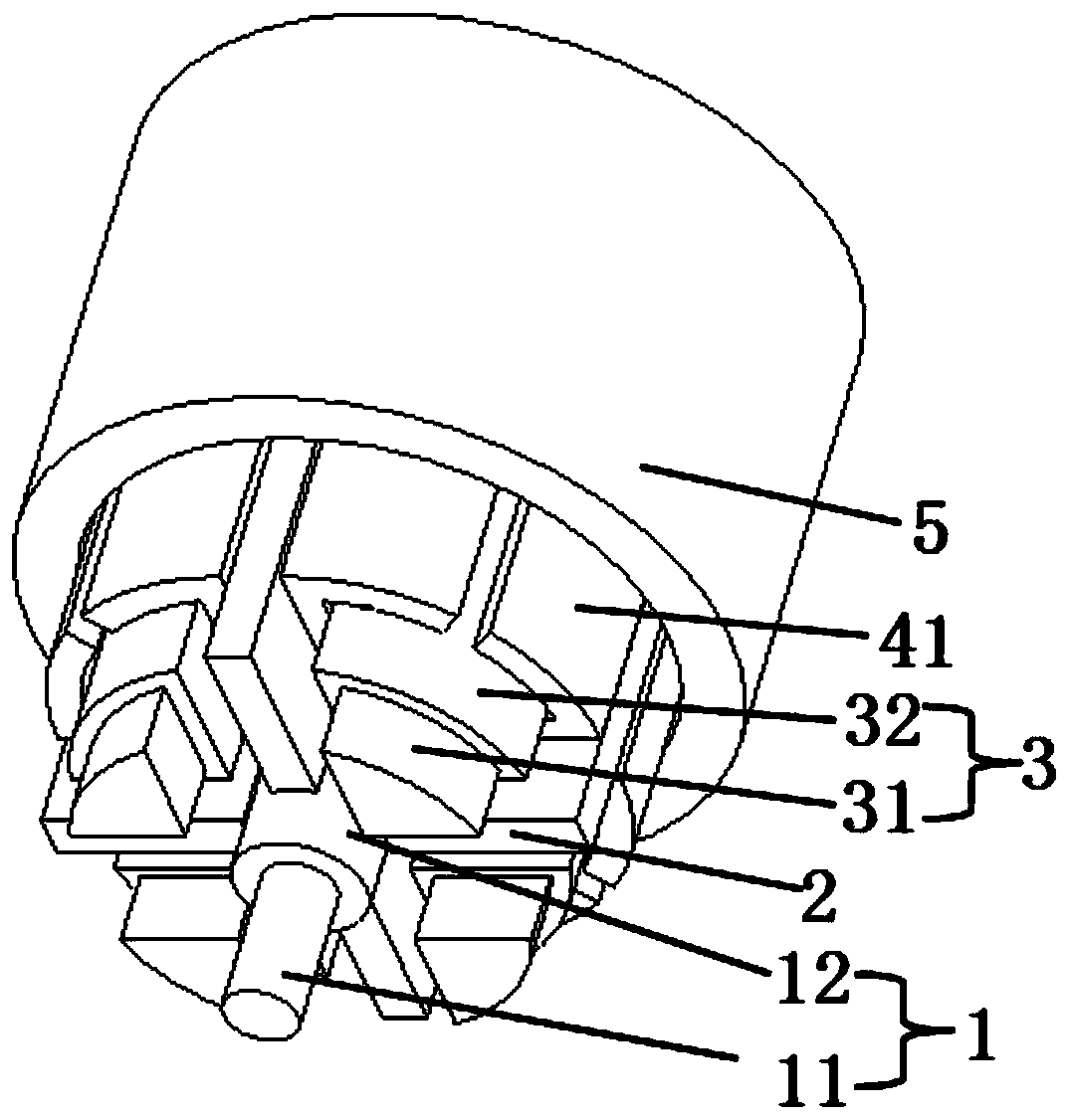
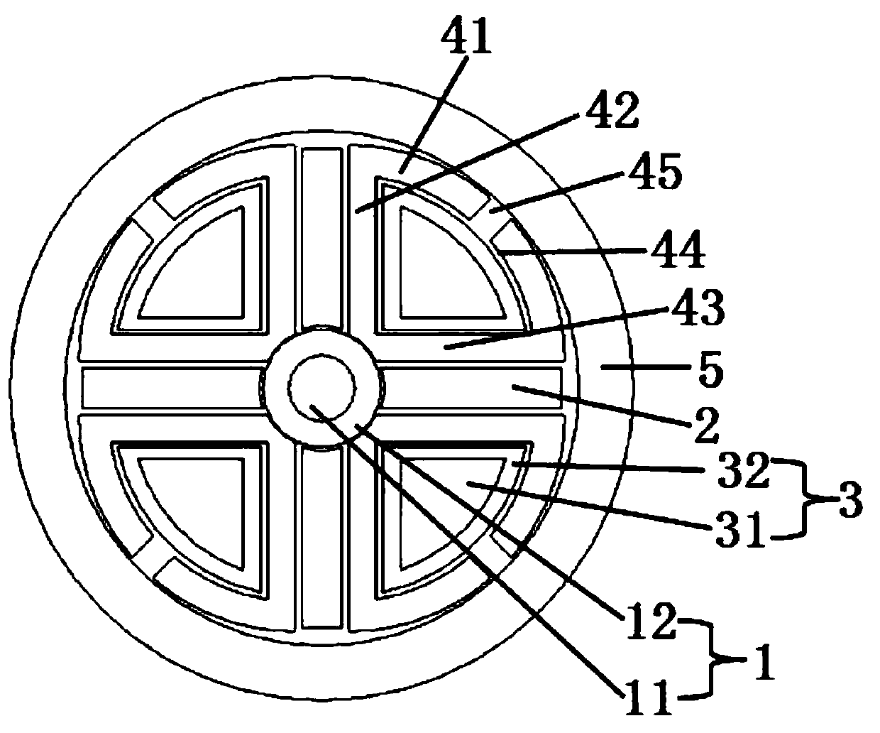
[0038] please see figure 1 and figure 2 , a fan-shaped heat dissipation cable, has a strengthening unit 1 located in the center, four power transmission bodies located outside the strengthening unit and evenly distributed, and an outer sheath 5 covering the power transmission body. The pad layer 12 coated outside the reinforcement is composed of an insulator and an electric unit 3 located in the insulator; it is characterized in that the cross section of the insulator is fan-shaped, and the insulator is composed of an arc cylinder 41, a first protection body 42, the second protection body 43 surrounds, the first protection body and the second protection body are cuboid shape, and the arc cylinder is the arc ring cylinder shape, and one end of the first protection body is connected with one end of the second protection body , the other end of the first protection body is connected to one end of the arc cylinder, the other end of the second protection body is connected to the ...

Embodiment 2

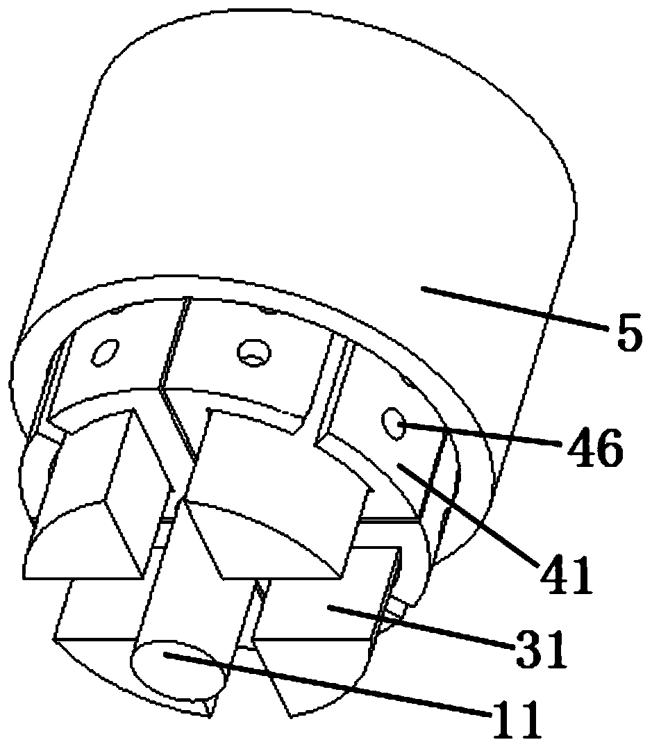
[0040] please see image 3 and Figure 4 , and refer to figure 1 and figure 2 , a fan-shaped heat dissipation cable, has a strengthening unit located in the center, four power transmission bodies located outside the strengthening unit and evenly distributed, an outer sheath 5 covering the power transmission body, the strengthening unit is a reinforcement 11, each power transmission The body is composed of an insulator and an electric unit 3 located in the insulator; it is characterized in that the cross section of the insulator is fan-shaped, and the insulator is surrounded by an arc cylinder 41, a first protection body 42, and a second protection body 43. The first protection body and The second protection body is in the shape of a cuboid, the arc cylinder is in the shape of an arc ring cylinder, one end of the first protection body is connected to one end of the second protection body, and the other end of the first protection body is connected to one end of the arc cylin...

Embodiment 3

[0043] please see Figure 5 and Figure 6 , and refer to Figure 1 to Figure 4, a fan-shaped heat dissipation cable, has a strengthening unit located in the center, four power transmission bodies located outside the strengthening unit and evenly distributed, an outer sheath 5 covering the power transmission body, the strengthening unit is a reinforcement 11, each power transmission The body is composed of an insulator and an electric unit 3 located in the insulator; it is characterized in that the cross section of the insulator is fan-shaped, and the insulator is surrounded by an arc cylinder 41, a first protection body 42, and a second protection body 43. The first protection body and The second protection body is in the shape of a cuboid, the arc cylinder is in the shape of an arc ring cylinder, one end of the first protection body is connected to one end of the second protection body, and the other end of the first protection body is connected to one end of the arc cylinde...


PUM


Abstract

The invention belongs to the technical field of electric power and cables, and relates to a fan-shaped heat dissipation cable. The fan-shaped heat dissipation cable is provided with a reinforcing unit, power transmission bodies and an outer sheath, wherein each power transmission body is composed of an insulator and an electric unit. The fan-shaped heat dissipation cable is characterized in that the insulator is enclosed by an arc column body, a first protection body and a second protection body, the first protection body and the second protection body are both cuboid-shaped, the arc column body is in an arc ring column body shape, one end of the first protection body is connected with one end of the second protection body, the first protection body is connected with the arc column body, the second protection body is connected with the arc column body, the arc column body is provided with heat dissipation grooves, the heat dissipation grooves are continuously distributed in the arc column body in the direction parallel to the axis, the top corner of the insulator is in a concave arc column shape, and the arc column body is provided with through inner heat dissipation holes; the electric unit is composed of a conductor with a fan-shaped cross section; and the power transmission bodies are attached to the reinforcing unit. The invention further discloses a fan-shaped heat dissipation optical cable. The fan-shaped heat dissipation cable has the main beneficial effects that the heat dissipation effect is better, the tear resistance is higher, the material consumption is lower,the diameter is smaller, the weight is lighter, and the cost is lower.

Description

technical field [0001] The invention belongs to the technical field of electric power and cables, and in particular relates to a fan-shaped cooling cable and a fan-shaped cooling optical cable. Background technique [0002] CN202584892U discloses an easy-to-open and strip parallel bundled optical fiber composite overhead insulated cable. When the cable needs to be photoelectrically separated during the erection process, it is only necessary to open the outer insulating sheath on the two sides of the installation pole on the optical unit core wire. Pull out the tearing rope from the opening on one side to tear and peel off the insulating sheath, and then pull the eccentric sheath along the groove on this side to cut off the fiber sleeve that needs to be separated. At this time, Pull out the cut fiber sleeve from the opening on the other side for subsequent lead-in. In the photoelectric separation process, the operator does not need to cut the entire cable to realize the phot...

Claims


Application Information

Patent Timeline
IPC IPC(8): H01B7/42H01B9/00H01B7/00H01B7/17H01B7/22G02B6/44
CPCG02B6/4432H01B7/0009H01B7/17H01B7/22H01B7/421H01B9/00
Inventor 凌卫康
Owner SUZHOU ZHUANCHUANG PHOTOELECTRIC TECH CO LTD
Why Eureka
Try Eureka