
Field plant ecological environment monitoring device

An environmental monitoring and plant technology, applied in the field of wild plant ecological environment monitoring, can solve the problems of urgent protection, easy erosion, time-consuming and labor-intensive, etc., and achieve the effect of being beneficial to protection and rescue, and ensuring the effectiveness and accuracy of detection.

Active Publication Date: 2020-06-02
XUCHANG UNIV
View PDF13 Cites 0 Cited by
  • Summary
  • Abstract
  • Description
  • Claims
  • Application Information

AI Technical Summary

Problems solved by technology

The study of the ecological environment is essential for the study of plants, the main contributors to photosynthesis, and with the intensification of human activities, the suitable ecological environment required by wild plants has become less and less, so the current The protection of plants is urgent. Based on this demand, regular field investigation and monitoring measures are generally used for supervision and protection. However, this form is time-consuming and laborious, and the protection effect is relatively general. Therefore, in order to adapt to the rapidly changing ecological environment, automatic monitoring technology is introduced. However, considering the problem that general soil sensors are easily eroded and invalidated after being inserted into the soil for a long time, a field plant ecological environment monitoring device that can accommodate soil sensors has been specially improved.

Method used


Image

  • Field plant ecological environment monitoring device
  • Field plant ecological environment monitoring device
  • Field plant ecological environment monitoring device

Examples


Embodiment 1

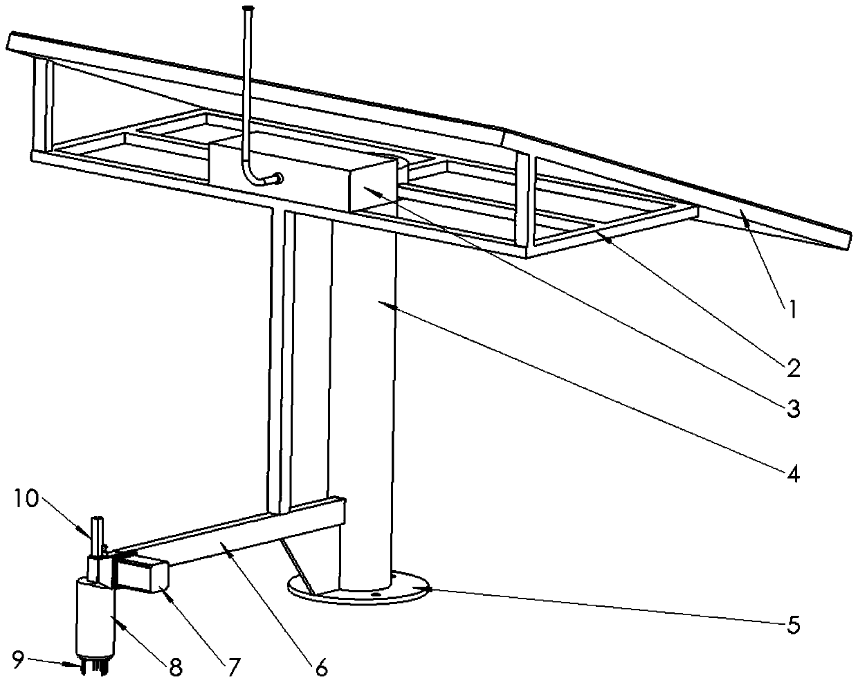
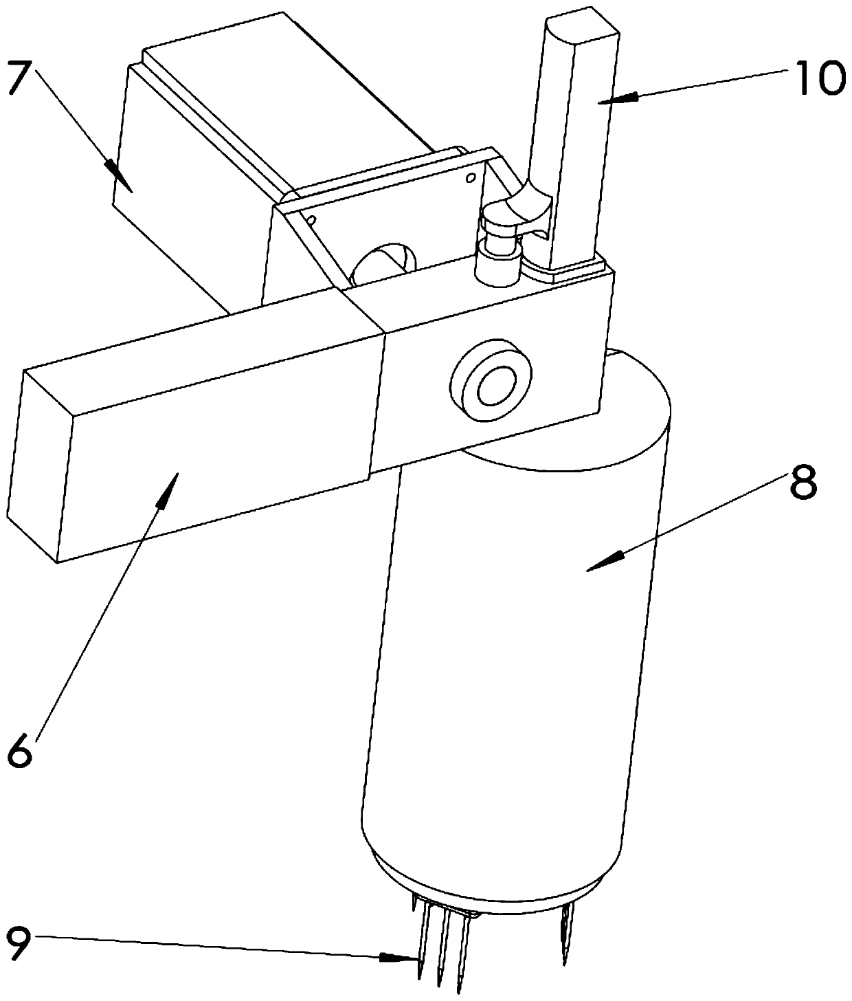
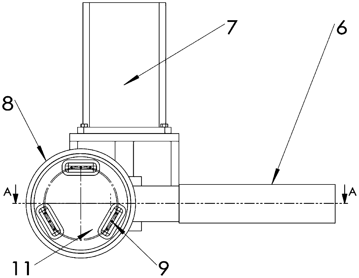
[0026] as attached figure 1 - attached Figure 4 As shown, the present invention provides a plant ecological environment monitoring device in the field, including a photovoltaic energy supply structure, a wireless controller 3, a bearing base, a cantilever monitoring base 18, a storage tube 8, a soil sensor 9, a rack movable rod 10, and a bearing plate 11. Rack movable rod 10, drive gear 15, servo motor 7, upstroke stop structure and downstroke stop structure, the carrying seat is respectively provided with a photovoltaic function structure and a cantilever monitoring seat 18, and the cantilever monitoring seat 18 is far away from the carrying seat Servomotor 7 is provided on the end of the servomotor 7, and the main shaft end of servomotor 7 stretches in the cantilever monitoring seat 18 and is provided with driving gear 15 on the end, and driving gear 15 is meshed with rack movable bar 10 in the cantilever monitoring seat 18;

[0027] The rack movable rod 10 extends vertica...


PUM


Abstract

The invention discloses a field plant ecological environment monitoring device which comprises a bearing base, a photovoltaic function structure and a cantilever monitoring base, wherein the photovoltaic function structure and the cantilever monitoring base are arranged on the bearing base; a servo motor is arranged at the end, away from the bearing base, of the cantilever monitoring base; a driving gear is arranged at the main shaft end of the servo motor; and the driving gear is engaged with a rack movable rod in the cantilever monitoring base; the upper end of the rack movable rod penetrates out of the cantilever monitoring base, the lower end of the rack movable rod extends into the storage barrel, a bearing disc is arranged at the end, located in the storage barrel, of the rack movable rod; and a plurality of soil sensors with different functions and downward detection heads are evenly distributed on the bearing disc around the vertical center line of the bearing disc; and the part, located above the cantilever monitoring base, of the rack movable rod and the part, located in the storage barrel, of the rack movable rod are provided with a lower stroke stop structure and an upper stroke stop structure respectively. The field plant ecological environment can be further monitored, the water content, the PH value and the temperature of soil can be automatically monitored, dataanalysis can be conveniently carried out in cooperation with remote sensing data, and field plant protection and rescue are facilitated.

Description

technical field [0001] The invention relates to the technical field of field plant ecological environment monitoring, in particular to a field plant ecological environment monitoring device. Background technique [0002] Ecology refers to the interconnection and interaction between organisms (prokaryotes, protists, animals, fungi, and plants) and between organisms and the surrounding environment. The concept of contemporary environment generally refers to geographical environment, which is the overall natural phenomenon surrounding human beings, and can be divided into natural environment, economic environment and social and cultural environment. Contemporary environmental science is a comprehensive science that studies the environment and its relationship with human beings. The study of the ecological environment is essential for the study of plants, the main contributors to photosynthesis, and with the intensification of human activities, the suitable ecological environme...

Claims


Application Information

Patent Timeline
Patent Type & Authority Applications(China)
IPC IPC(8): G01N33/24G01K13/00G01D11/00
CPCG01N33/24G01N33/246G01K13/00G01D11/00Y02E10/56
Inventor 王蒙
Owner XUCHANG UNIV
Learn More