Anti-stealing safety lock for electric meter box
A meter box and anti-stealing technology, which is applied to building locks, measuring electrical variables, and locks controlled by non-mechanical transmissions. stable effect
- Summary
- Abstract
- Description
- Claims
- Application Information
AI Technical Summary
Problems solved by technology
Method used
Image
Examples
Embodiment 1
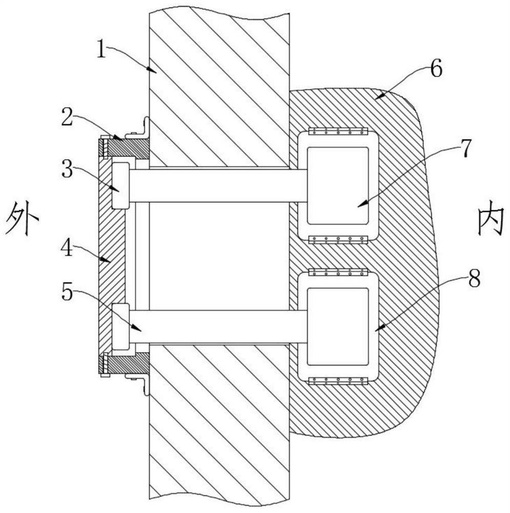
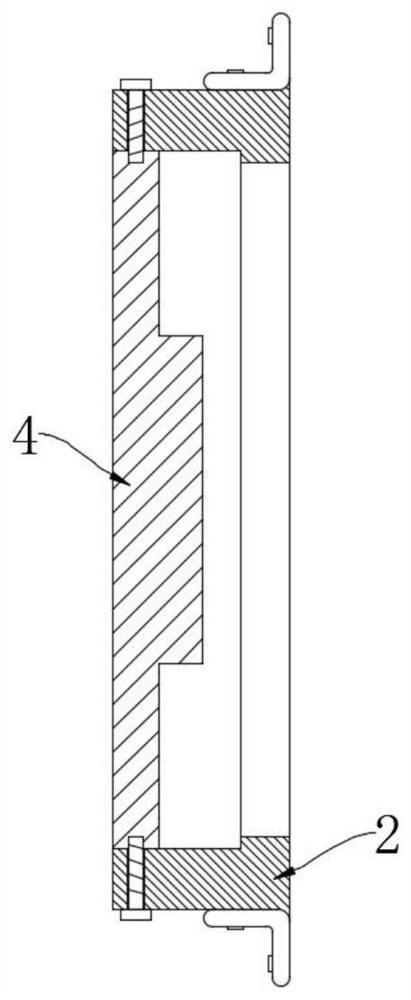
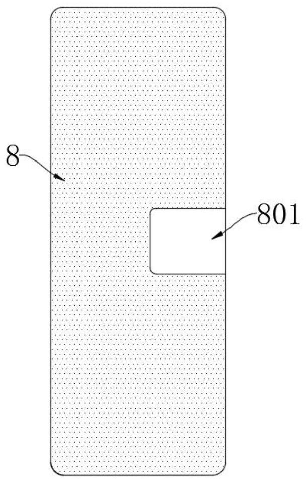
[0032] Such as Figure 1-5 As shown, an anti-theft safety lock for an electric meter box includes a fixed seat 2 fixedly installed on the electric meter box door 1 and two fixed plates 8 fixedly installed on the electric meter box wall 6, and the electric meter box door 1 is provided with There are two connecting rods 5 that go through the groove and are movable in the through groove. The two ends of each connecting rod 5 are fixedly connected with the connecting head 3 and the fixing block 7 respectively, and the two connecting heads 3 are all slidably arranged on the fixing seat 2 Inside, the corresponding fixed block 7 and the fixed plate 8 are jointly provided with an anti-theft component;
[0033] Each anti-theft assembly includes a limit groove 801 opened on the corresponding fixed plate 8 and a first cylindrical groove 701 and an installation groove 702 opened on the corresponding fixed block 7, and each installation groove is aligned with the corresponding first column...
Embodiment 2
[0043] Such as Figure 6-8 As shown, the difference between this embodiment and Embodiment 1 is that a third cylindrical groove 802 is also opened in each fixing plate 8, and a second molded groove 802 is elastically connected with a second spring in the third cylindrical groove 802. Steel pipe 12, the second cast steel pipe 12 is also provided with permanent magnets, and each fixed block 7 is provided with a second cylindrical groove 703 matching the specification of the corresponding third cylindrical groove 802, and the second cylindrical The magnetic block 14 is arranged in the groove 703 .
[0044] The second excitation coil 13 is fixedly installed in each installation groove 702, and the central axis of the second excitation coil 13 and the central axis of the corresponding magnetic block 14 are located on the same straight line, and each second excitation coil 13 is connected to the connector Electrically connected, the winding directions of the wires on the outside of...
PUM
 Abstract
Description
Claims
Application Information
 - R&D Engineer
- R&D Manager
- IP Professional
- Industry Leading Data Capabilities
- Powerful AI technology
- Patent DNA Extraction
Browse by: Latest US Patents, China's latest patents, Technical Efficacy Thesaurus, Application Domain, Technology Topic, Popular Technical Reports.
© 2024 PatSnap. All rights reserved.Legal|Privacy policy|Modern Slavery Act Transparency Statement|Sitemap|About US| Contact US: help@patsnap.com


