Sanding device for locomotive

A technology of sand spreading device and locomotive, which is applied in the direction of locomotives, etc., which can solve the problems of clogging of sand blowing nozzles, affecting vehicle driving safety, and affecting normal sand spreading, etc., so as to prolong service life, improve sand spreading efficiency, and avoid vertical impact wear effect

Active Publication Date: 2020-06-02
HUNAN LIANCHENG TRACK EQUIP CO LTD +1
View PDF9 Cites 0 Cited by
  • Summary
  • Abstract
  • Description
  • Claims
  • Application Information

AI Technical Summary

Problems solved by technology

For example, when the sand spreader is turned off, the sand stirring nozzle is easily blocked by the raised sand, which affects the normal sand spreading and seriously affects the driving safety of the vehicle.
Moreover, because the sand blasting nozzle directly sprays sand particles and impacts the internal cavity, there is a risk of blowing through the side wall of the cavity
In addition, the sand stored in the cavity will be wet or hardened if it is not used for a long time, which will affect the sanding effect and affect the driving safety of the vehicle

Method used


Image

  • Sanding device for locomotive
  • Sanding device for locomotive
  • Sanding device for locomotive

Examples


Embodiment Construction

[0025] The present invention is introduced below by accompanying drawing.

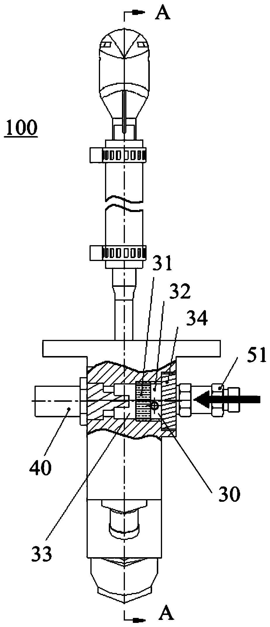
[0026] In this application, it should be noted that the directional terms or qualifiers "upper end" and "lower end" used in this application all refer to the attached figure 1 In terms of. They are not intended to define the absolute positions of the parts involved, but may vary on a case-by-case basis. In addition, the vertical direction is attached figure 1 the vertical direction.

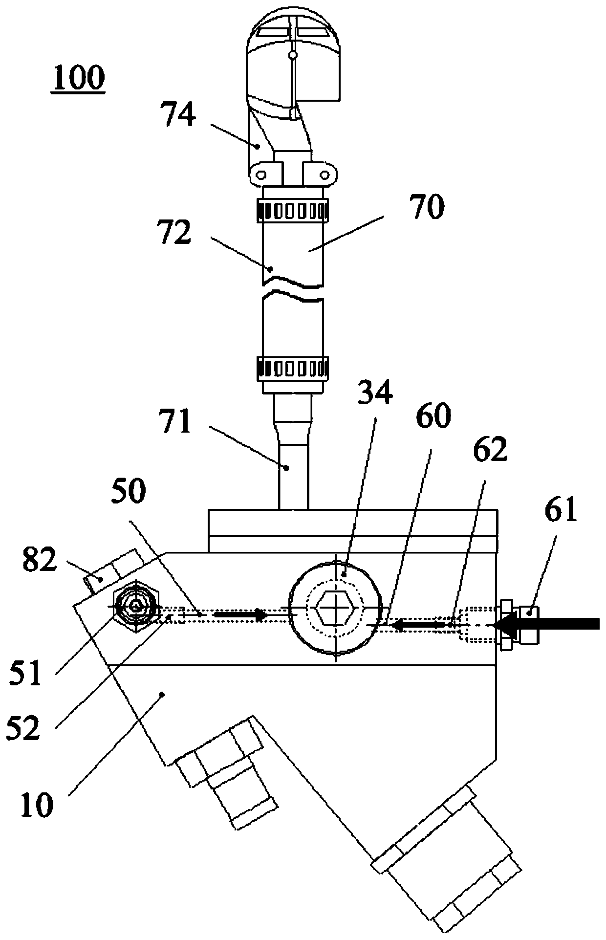
[0027] figure 1 The structure of the sand spreading device 100 for a locomotive according to the present invention is shown. The sand spreading device 100 is used to be connected under the locomotive sand box 200 . Such as figure 1 As shown, the sanding device 100 includes a sanding body 10 which, in one embodiment, is configured in a generally triangular shape. A mounting plate 11 is fixedly connected to the upper end of the sand spreading main body 10 . A number of mounting holes are provided on the mounting pla...


PUM


Abstract

The invention provides a sanding device for a locomotive, which comprises a sanding main body, a plurality of sanding nozzles and a plurality of sanding nozzles, the air inlet cavity is arranged in the sanding main body and is respectively communicated with the sanding runner and the locomotive sand box, and a heater is arranged in the air inlet cavity; the first air inlet flow channel and the second air inlet flow channel are respectively communicated with the air inlet cavity; the sanding air cavity is communicated with the first air inlet flow channel, a sanding air nozzle is arranged in the sanding air cavity, and the spraying direction of the sanding air nozzle faces the sand outlet of the sanding flow channel; wherein in the first working state, the normal-pressure sanding air sourceenters the sanding air cavity and enters the sanding flow channel through the first air inlet flow channel to be stirred, and sand grains are blown out under the combined action of the sanding air nozzle, so that sanding operation is carried out; and in the second working state, the normal-pressure air source enters the air inlet cavity through the second air inlet flow channel and enters the locomotive sand box and the sanding flow channel after being heated by the heater, so that sand grains are kept loose and dry.

Description

technical field [0001] The invention relates to the technical field of track equipment, in particular to a sand spreading device for locomotives. Background technique [0002] The sand spreader is used to spread sand between the wheel tread and the wheel rail, so as to improve the adhesion coefficient between the wheel and rail of the locomotive, thereby effectively inhibiting the idling of the wheel set, improving the traction performance, and effectively ensuring the transportation capacity and driving safety of the locomotive. The principle of the existing sand spreader is to use two ways, wherein, one way is to stir up the sand particles in the cavity of the sand spreader through the sand stirring nozzle, and the other way is to blow out the stirred up sand particles through the sand blowing nozzle, so as to realize the dusting effect. sand. [0003] However, the existing sand spreaders still have the following problems. For example, at the moment when the sand spreade...

Claims


Application Information

Patent Timeline
Patent Type & Authority Applications(China)
IPC IPC(8): B61C15/10
CPCB61C15/102
Inventor 王晟晟侯知青刘肖
Owner HUNAN LIANCHENG TRACK EQUIP CO LTD
Why Eureka
Try Eureka