Medical orthopedic bandage winding device

A winding device and medical technology, applied in the medical field, can solve the problems that the degree of tightness and tightness of the wrapping cannot be unified, the height and position of the wrapping device cannot be adjusted, and the wrapping is slow, so as to achieve the effect of conveniently moving the wrapping device

Inactive Publication Date: 2020-06-02
李卓
View PDF0 Cites 11 Cited by
  • Summary
  • Abstract
  • Description
  • Claims
  • Application Information

AI Technical Summary

Problems solved by technology

[0002] With the development and progress of science and technology, orthopedics has made great progress in diagnosis and treatment. Orthopedics is also called orthopedics. Bandages are the most common medical supplies in orthopedic departments of hospitals. They are mainly used for The dressing of various wounds can stop bleeding and prevent infection from contact with bacteria. The daily work in the hospital is relatively complicated, and the staff are very busy. Using bandages to bandage wounds is one of the most common tasks for medical staff in the orthopedic department. Traditional Many people bandage the wound, the bandage is relatively slow, and the degree of tightness and tightness cannot be uniform. At present, most of the bandage wrapping devices used are relatively simple in structure, and the height and position of the wrapping device cannot be adjusted according to the height of different patients, which has great limitations. sex

Method used


Image

  • Medical orthopedic bandage winding device
  • Medical orthopedic bandage winding device
  • Medical orthopedic bandage winding device

Examples


Embodiment Construction

[0015] The technical solution of this patent will be further described in detail below in conjunction with specific embodiments.

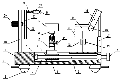
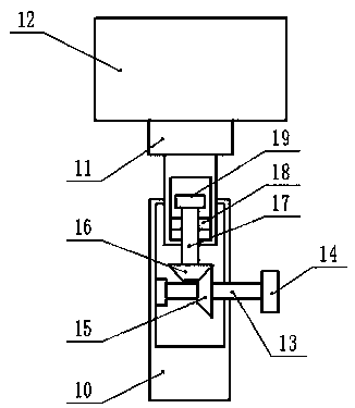
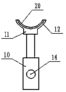
[0016] see Figure 1-3 , a medical orthopedic dressing bandage winding device, comprising a base 1, a first threaded rod 5, a slider 9, a lifting device 10, a second gear 16, a locker 21 and a motor 29; Four universal wheels 2 are installed on the cloth, and a brake pedal 3 is arranged on the universal wheels 2. By setting the universal wheels 2, it is more convenient to move the device, saving time and effort. The base 1 is provided with a chute 4, and the chute 4 is installed with the first threaded rod 5, the left side of the first threaded rod 5 is connected with the base 1 through the bearing seat 6, the right side of the first threaded rod 5 is equipped with the first rotary valve 7, the first threaded rod 5 A first threaded sleeve 8 is installed on the first threaded sleeve 8, and a slide block 9 is installed on the first threaded sleeve 8....


PUM


Abstract

The invention discloses a medical orthopedic bandage winding device. The device comprises a base, a first threaded rod, a sliding block, a lifting device, a second gear, a storage cabinet and a motor;four universal wheels are uniformly arranged around the lower part of the base; a first rotary valve is arranged on the right side of the first threaded rod; the lifting device is arranged on the sliding block; the second gear is arranged above the first gear; a first limiting block is arranged above the second threaded rod; a fixed seat is arranged on the lifting device; an arc-shaped supportingplate is arranged on the fixed seat; the storage cabinet is arranged at the right side of the lifting device; a seat is arranged on the storage cabinet; a back rest is arranged on the right side of the storage cabinet; the back rest is connected with the seat through a hinge pin; a support frame is arranged on the left side of the upper part of the seat; a motor is arranged on the left side of the upper part of the support frame; and a second rotating shaft is arranged on the right side of the motor. The storage cabinet provided by the invention can be used for conveniently placing medicinesfor binding and winding bandages.

Description

technical field [0001] The invention relates to the medical field, in particular to a medical orthopedic dressing bandage winding device. Background technique [0002] With the development and progress of science and technology, orthopedics has made great progress in diagnosis and treatment. Orthopedics is also called orthopedics. Bandages are the most common medical supplies in orthopedic departments of hospitals. They are mainly used for The dressing of various wounds can stop bleeding and prevent infection from contact with bacteria. The daily work in the hospital is relatively complicated, and the staff are very busy. Using bandages to bandage wounds is one of the most common tasks for medical staff in the orthopedic department. Traditional Many people bandage the wound, the bandage is relatively slow, and the degree of tightness and tightness cannot be uniform. At present, most of the bandage wrapping devices used are relatively simple in structure, and the height and p...

Claims


Application Information

Patent Timeline
Patent Type & Authority Applications(China)
IPC IPC(8): A61F15/00A61G12/00
CPCA61F15/005A61F15/007A61G12/00
Inventor 李卓
Owner 李卓
Why Eureka
Try Eureka