
Video synchronous display method and system

A technology of video synchronization and display method, which is applied in the direction of digital output to display equipment, static indicators, cathode ray tube indicators, etc., which can solve time-consuming problems and achieve the effect of reducing frame synchronization verification time

Active Publication Date: 2020-05-29
JINGGANGSHAN ELECTRIC CO LTD
View PDF5 Cites 1 Cited by
  • Summary
  • Abstract
  • Description
  • Claims
  • Application Information

AI Technical Summary

Problems solved by technology

[0007] The present invention provides a video synchronous display method and system, which is used to solve the need to produce videos with time stamps or frame stamps in the prior art, and professional testers take pictures continuously to judge. This method is very expensive in the product development stage a matter of time

Method used


Image

  • Video synchronous display method and system
  • Video synchronous display method and system
  • Video synchronous display method and system

Examples


Embodiment Construction

[0037] The technical solutions of the present invention will be described in detail below through the accompanying drawings and specific embodiments. It should be understood that the embodiments of the present invention and the specific technical features in the embodiments are only descriptions of the technical solutions of the present invention, rather than limitations. , the embodiments of the present invention and specific technical features in the embodiments may be combined with each other.

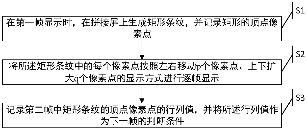
[0038] Such as figure 1 Shown is a flow chart of a video synchronous display method in an embodiment of the present invention, the method comprising:

[0039] S1, when the first frame is displayed, generate rectangular stripes on the splicing screen, and record the vertex pixels of the rectangle;

[0040] S2, displaying each pixel in the rectangular stripes frame by frame in a display mode of moving p pixels left and right and expanding q pixels up and down;

[0041] S3. Record th...


PUM


Abstract

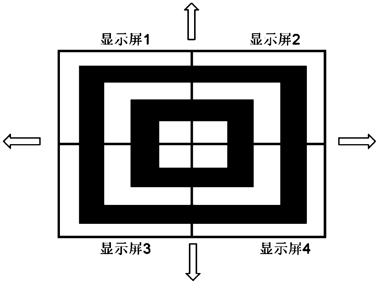
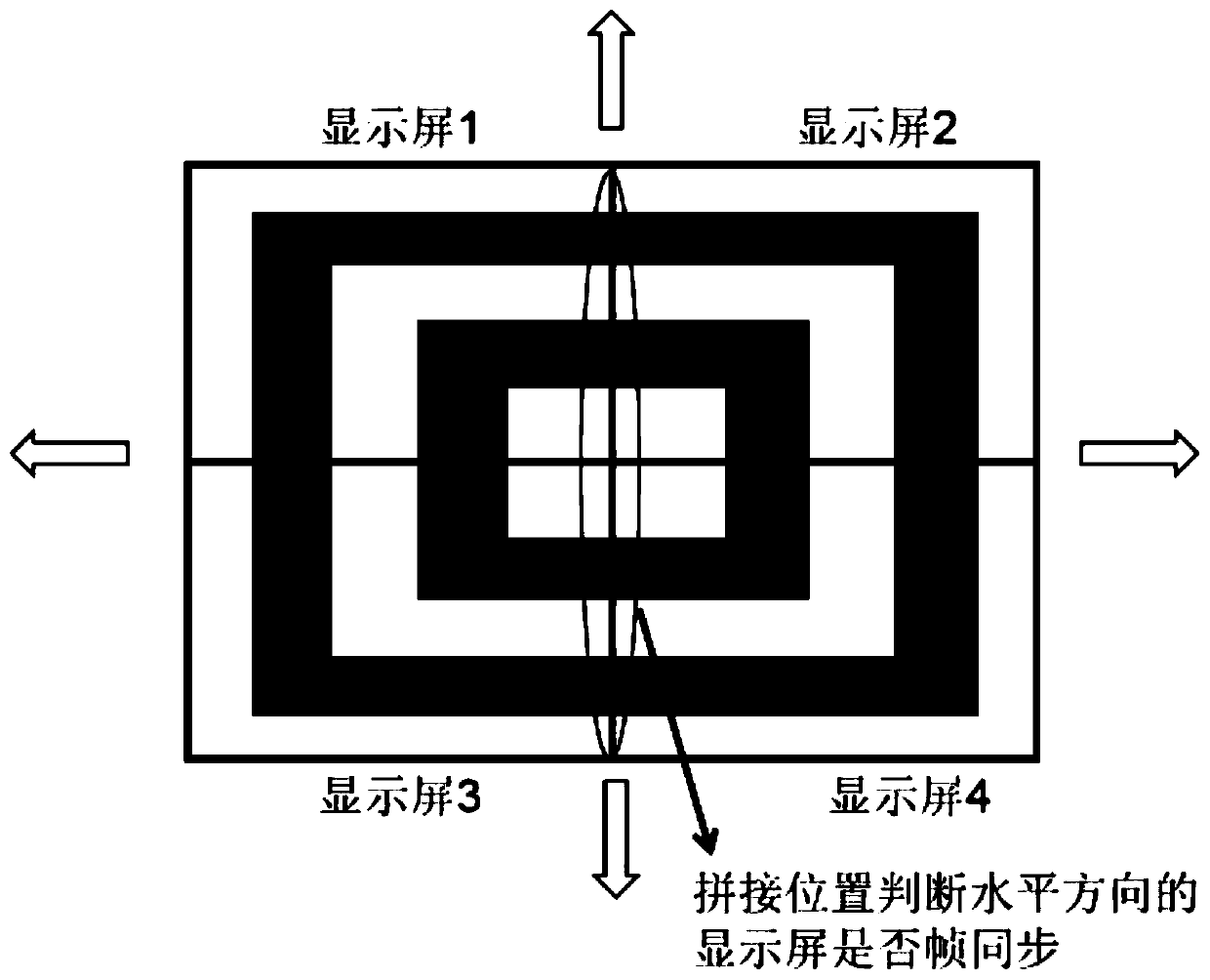
The invention discloses a video synchronous display method and system. The method is based on the method provided by the invention. When synchronous verification of the spliced screen is carried out,output frame synchronization of the video segmentation equipment is judged through rectangular stripes which diffuse outwards from a central point at a constant speed and are continuously circulated.The method is simpler and more intuitive, and can be easily judged only by human eyes, and when frames are asynchronous, the dislocation difference of stable movement exists at the splicing position of each display screen, so that not only is the mode of adding a timestamp or a frame stamp into a video avoided, but also the frame synchronization verification time of a user or a worker is reduced.

Description

technical field [0001] The present application relates to the technical field of video display, in particular to a video synchronous display method and system. Background technique [0002] Video splicing equipment is required in applications such as TV walls and multi-screen projections. It divides the input video signal in real time, and then synchronously outputs different images to different display devices. These divided images need to be frame-synchronized, so as to reduce the sense of tearing and dislocation between multiple images. [0003] The traditional method of judging whether each splicing screen is frame-synchronized is to play a video source with a time stamp or frame stamp, and after splitting through the video splicing device, the tester judges the time stamp or frame stamp by taking pictures continuously Whether they are the same, if they are the same, it means that the frame is synchronized, otherwise, it is not synchronized. [0004] The existing metho...

Claims


Application Information

Patent Timeline
Patent Type & Authority Applications(China)
IPC IPC(8): G06F3/14G09G5/14
CPCG06F3/1446G09G5/14
Inventor 谢新辉
Owner JINGGANGSHAN ELECTRIC CO LTD
Learn More