
Directional drilling system and directional drilling method

A drill bit and rotating rod technology, applied in the field of geological exploration, can solve problems such as troublesome operation, and achieve the effect of improving sampling efficiency and reducing wear and tear

Pending Publication Date: 2020-05-29
中煤浙江勘测设计有限公司
View PDF5 Cites 6 Cited by
  • Summary
  • Abstract
  • Description
  • Claims
  • Application Information

AI Technical Summary

Problems solved by technology

[0004] The above-mentioned existing technical solutions have the following defects: in the sampling process, it is necessary to drive the fixed drill bit into the ground through the first electric telescopic rod and the fixed motor, so as to fix the device; The servo motor drives the sampling rod deep into the ground for sampling
Soil sampling requires workers to operate four sets of fixed motors, four sets of first electric telescopic rods, servo motors and second electric telescopic rods in sequence. The operation is more troublesome, so it needs to be improved.

Method used


Image

  • Directional drilling system and directional drilling method
  • Directional drilling system and directional drilling method
  • Directional drilling system and directional drilling method

Examples


Embodiment 1

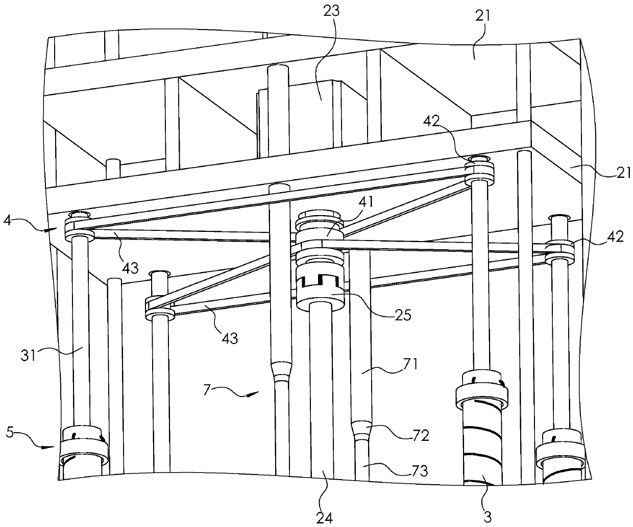
[0043] Embodiment one: if figure 1 As shown, the directional drilling system includes a frame 1, a sampling assembly 2 and several rollers 11 installed at the bottom of the frame 1, and the sampling assembly 2 includes a mounting frame 21, a lifting piece, a servo motor 23 and a sampling rod 24; the lifting piece is along the The electric cylinder 22 extending in the vertical direction is fixed on the frame 1, and the piston rod of the electric cylinder 22 is fixedly connected to the upper surface of the mounting frame 21; the servo motor 23 is fixed at the bottom of the mounting frame 21; the sampling rod 24 passes through the coupling 25 Connected to the output shaft of the servo motor 23; both sides of the frame 1 are equipped with counterweight irons 12.

[0044] Such as figure 1 As shown, the mounting bracket 21 is rotatably connected with some rotating rods 31 that are circumferentially arranged around the sampling rod 24. In this embodiment, the number of rotating rods...

Embodiment 2

[0056] Embodiment two: directional drilling method, such as Figure 1 to Figure 3 shown, including the following steps:

[0057] S1. First push the frame 1 to the designated position, then drive the sampling rod 24 to rotate through the servo motor 23, and drive the installation frame 21, the sampling rod 24, the rotating rod 31 and the drill bit 3 to descend synchronously through the electric cylinder 22;

[0058] S2, impel the rotating rod 31 and the drill bit 3 to rotate through the linkage of the synchronous belt 43, so that the drill bit 3 rotates and drills into the ground;

[0059] S3. When the push ring 54 descends and presses against the disengagement member 6, the spring 55 will be compressed and the push surface 541 will be disengaged from the clamping member 52, and then the clamping member 52 will be disengaged from the clamping groove 53, so that the rotating rod 31 is in the Rotate and descend in the accommodation chamber 32;

[0060] S4, when the timing belt ...


PUM


Abstract

The invention relates to a directional drilling system and a directional drilling method. The directional drilling system comprises a rack, a sampling assembly and a plurality of idler wheels, the sampling assembly comprises a mounting frame, a lifting piece, a servo motor and a sampling rod, the mounting frame is rotationally connected with a plurality of rotating rods, drill bits are arranged atthe bottoms of the rotating rods, and a containing cavity and a clamping assembly are arranged on each drill bit; and the rack is provided with a linkage assembly, a plurality of disengaging pieces,a plurality of limiting pieces and a plurality of driving pieces. In the sampling process, the sampling rod is driven by the servo motor to rotate firstly, then the mounting frame is driven by the lifting piece to descend, then the clamping assembly moves to abut against the disengaging pieces, the drill bits are fixed underground, and the sampling rod rotates to go deep into the underground position for soil sampling. After sampling is completed, the sampling rod is driven by the servo motor to rotate reversely, the mounting frame is driven by the lifting piece to ascend, and the sampling rodis rotated out from the underground position, so that soil sampling is completed. The directional drilling system and the directional drilling method improve the sampling efficiency.

Description

technical field [0001] The invention relates to the technical field of geological survey, in particular to a directional drilling system and a directional drilling method. Background technique [0002] In the process of geological exploration, it is necessary to sample and analyze the soil quality. The existing sampling device has a rigid structure and single function, which is not convenient for geological survey. [0003] Through retrieval, Chinese Patent Announcement No. CN109060416A discloses a drilling sampling device for geological exploration, including a lifting mechanism and a fixing mechanism. Bottom plate, sampling hole, limit slider, buffer spring, limit pin, first fixed plate, second fixed plate, fixed top plate, counterweight iron, fixed chute, first electric telescopic rod, fixed slider, lifting slider The structure of the present invention is compact, and it is convenient for use in geological surveys. By setting up a fixed motor and a fixed drill bit, it is...

Claims


Application Information

Patent Timeline
IPC IPC(8): E21B49/02E21B7/04E21B7/02E21B15/00
CPCE21B49/02E21B7/04E21B7/027E21B15/00Y02P70/10
Inventor 陈必权陈寒勇何万通王利斌
Owner 中煤浙江勘测设计有限公司
Learn More