A display stand and its manufacturing method

A display stand and display frame technology, applied in manufacturing tools, display shelves, display hangers, etc., can solve problems such as troubles, and achieve the effects of improving safety performance, improving functional diversity, and improving safety.

Active Publication Date: 2020-12-08
上海明勤金属制品有限公司
View PDF12 Cites 0 Cited by
  • Summary
  • Abstract
  • Description
  • Claims
  • Application Information

AI Technical Summary

Problems solved by technology

[0004] The above-mentioned existing technical solutions have the following defects: the operator can place the books in the above-mentioned space, but the managers and exhibitors can only take the books out of the above-mentioned space and read them in their hands to learn about the book's publishing house, The specific information such as the cover pattern, the back cover pattern, and the publication date of the back cover are very troublesome

Method used


Image

  • A display stand and its manufacturing method
  • A display stand and its manufacturing method
  • A display stand and its manufacturing method

Examples


Embodiment 1

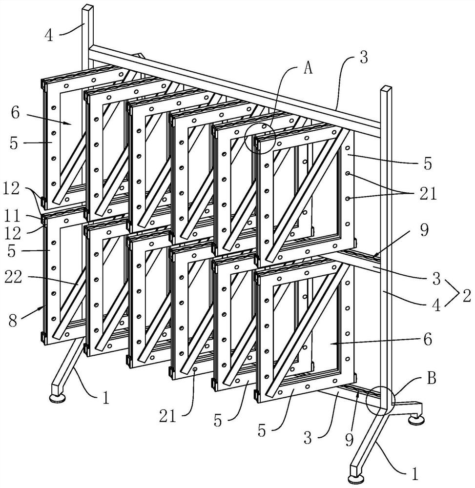
[0041] Embodiment 1: a display stand, such as figure 1 As shown, it includes a base 1 and a plurality of frame bodies 2 arranged on the base 1 . Wherein, the base 1 has four brackets made of stainless steel (not marked in the figure), and the bottom of each bracket is fixed with a disc-shaped bracket pad. In addition, each frame body 2 is mainly a ring-shaped structure composed of three beams 3 and two vertical rods 4, and a plurality of ring-shaped display frames 5 are rotatably connected in each middle frame body 2, and each display frame 5 It is made of stainless steel, and a rectangular through hole 6 is opened in the middle of each display frame 5, and the operator can observe and obtain the information of the items to be displayed through the through hole 6, which is very convenient.

[0042] like figure 1 It can be seen that in order to improve the diversity of functions of the display frame 5 , a plurality of circular openings 21 are opened on the display frame 5 . ...

Embodiment 2

[0052] Embodiment 2: a display rack, the difference from Embodiment 1 is: as Figure 5 As shown, in order to present a variety of different visual angles to the exhibitors, the display frame 5 is detachably connected with a U-shaped block 18 on the side close to the short axis 7, and the side wall of the display frame 5 is along the side wall of the display frame 5. The height direction is slidingly connected in the U-shaped block 18 , and the display frame 5 is in conflict with the bottom of the U-shaped block 18 near the side wall of the U-shaped block 18 . at the same time as Figure 5 As shown, a horizontal threaded hole (not marked in the figure) is opened in the center of the U-shaped block 18, and a bolt 19 is screwed in the threaded hole, and the head of the bolt 19 abuts against the U-shaped On the outer wall of the clamping block 18 , the other end passes through the threaded hole and is screwed on the side wall of the display frame 5 . Thus, the operator can first...


PUM


Abstract

The invention, whichbelongs to the technical field of display tools, relates to a showing stand and a manufacturing method thereof. The showing stand comprises a pedestal and a plurality of frame bodies. Each frame body mainly has an annular structure composed of a plurality of cross beams and vertical rods. A display frame is rotationally connected into each frame body and provided with a throughhole, the two ends of each display frame are provided with short shafts respectively, one end of each short shaft is connected to the corresponding display frame, and the other end of each short shaft is rotationally connected to the inner wall of the corresponding frame body; and an inserting groove is formed in the display frame. The manufacturing method comprises the steps that a pedestal, frame bodies and a U-shaped clamping block are manufactured; an inserting groove, a circular opening and a threaded hole are formed; a sliding groove is formed in each frame body, and a kidney-shaped hole is formed in the U-shaped block; the U-shaped block is welded to each frame body; and assembling and forming are carried out. According to the invention, more articles can be displayed, and the displayed articles can be displayed in a multi-angle and omnibearing manner through rotation and the like, so that an operator can store and search products more conveniently and quickly.

Description

technical field [0001] The invention belongs to the technical field of display appliances, and more specifically relates to a display stand and a manufacturing method thereof. Background technique [0002] At present, display racks can be used to display items from multiple angles and all directions, such as books, periodicals, magazines, etc., and even fabrics such as fabric samples and silk scarves. The display stand can be used in exhibitions or counters and windows, and is deeply loved by consumers. [0003] The existing display stand includes a base and a plurality of frame bodies arranged on the base. The frame body is mainly a ring structure composed of a plurality of beams and vertical rods, and a baffle plate is provided on one side of the frame body. At this moment, a space for placing books is formed between the baffle plate, the beam and the vertical pole. [0004] The above-mentioned existing technical solutions have the following defects: the operator can pla...

Claims


Application Information

Patent Timeline
Patent Type & Authority Patents(China)
IPC IPC(8): A47F5/02A47F5/10A47F7/00A47F11/00B23P15/00B23P19/00
CPCA47F5/02A47F5/10A47F7/00A47F11/00B23P15/00B23P19/00
Inventor 刘富强孔凡龙朱素连范峰
Owner 上海明勤金属制品有限公司
Why Eureka
Try Eureka