


Quick Research
Generate reliable direction feasibility study reports for your R&D in just a few steps.

Technical Q&A
Discover and master advanced knowledge NOW. Basics, ideas, possibilities, all at once.

Find Solutions
As an expert in R&D theories, this can generate solutions to your technical problems instantly.

Evaluate Feasibility
Analyze your overall solution with one click, know your potential R&D risks in advance.

Monitor Landscape
Get weekly tech updates, stay abreast of the latest tech innovations and key insights.
Refrigeration device
一种制冷装置、制冷剂的技术,应用在制冷机、制冷组件、制冷和液化等方向,能够解决制冷剂起火等问题
- Summary
- Abstract
- Description
- Claims
- Application Information
AI Technical Summary
Problems solved by technology
Method used
Image

Examples
no. 1 approach
[0058] The first embodiment will be described. This embodiment is an air conditioner 10 constituted by a refrigeration device.
[0059] -Construction of air conditioner-
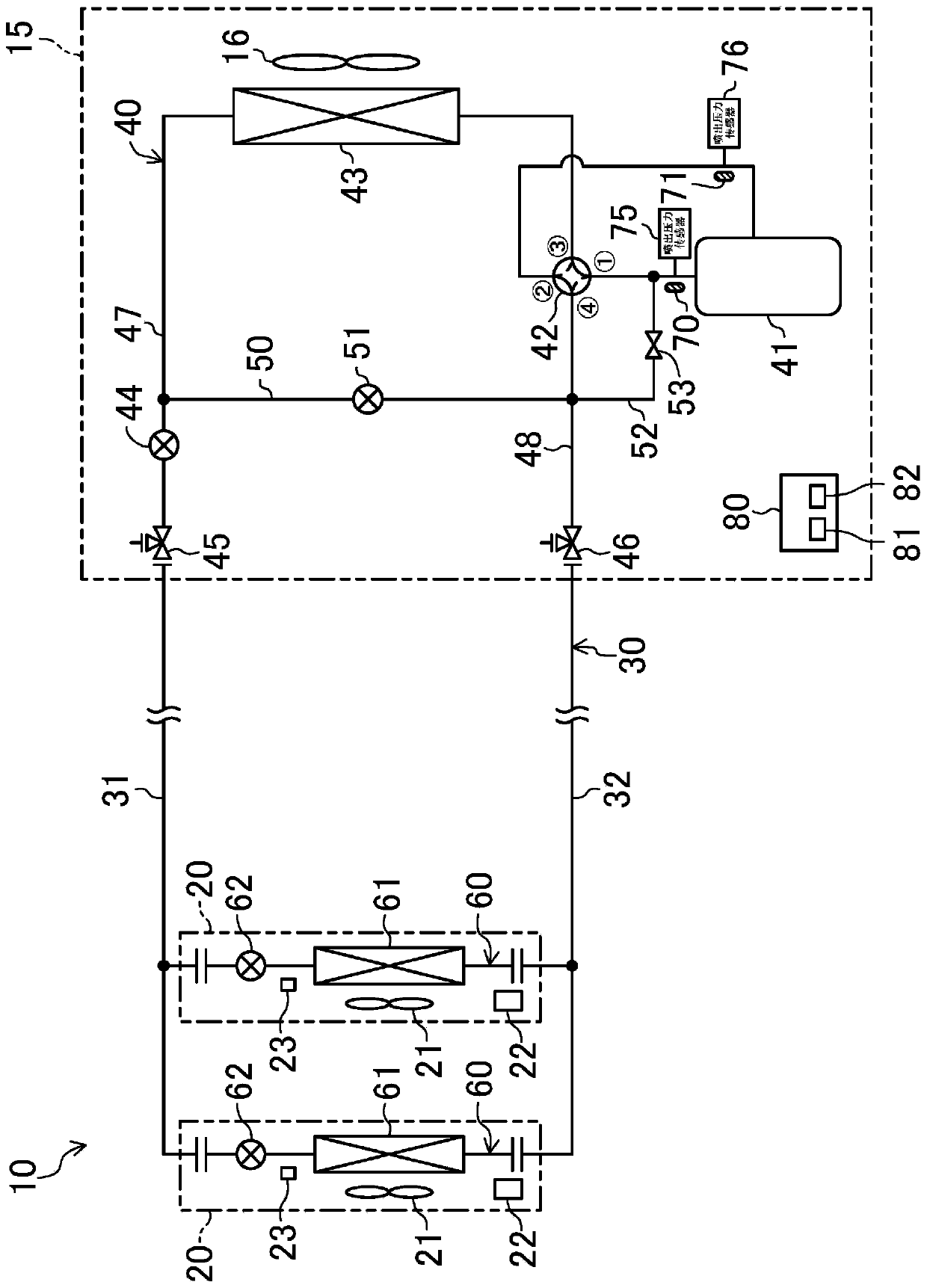
[0060] Such as figure 1 As shown, the air conditioner 10 of this embodiment includes one outdoor unit 15 and a plurality of indoor units 20 . It should be noted, figure 1 The number of outdoor units 15 and the number of indoor units 20 shown are just examples. In other words, the air conditioner 10 may be provided with a plurality of outdoor units 15 , or may be provided with one or more than three indoor units 20 .
[0061]
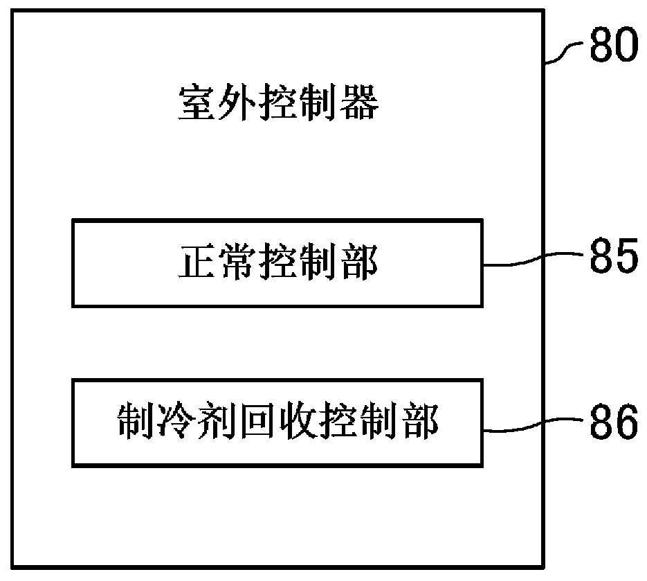
[0062] The outdoor unit 15 constitutes a heat source side unit. The outdoor unit 15 is provided with an outdoor circuit 40 , an outdoor fan 16 , and an outdoor controller 80 . The outdoor fan 16 constitutes a heat source side fan and supplies outdoor air to an outdoor heat exchanger 43 described later. The outdoor circuit 40 and the outdoor controller 80 will be described later....
no. 2 approach
[0122] A second embodiment will be described. The air conditioner 10 of the present embodiment is obtained by changing the configuration of the outdoor circuit 40 in addition to the air conditioner 10 of the first embodiment. Here, differences between the air conditioner 10 of the present embodiment and the air conditioner 10 of the first embodiment will be described.
[0123] Such as Figure 4 As shown, in the air conditioner 10 of the present embodiment, the liquid reservoir 57 and the bypass switching valve 58 are provided on the liquid side bypass pipe 50 of the outdoor circuit 40 . The liquid reservoir 57 is arranged in the part of the liquid side bypass pipe 50 in this embodiment closer to the liquid side pipe 47 than the liquid side bypass valve 51, and the bypass switch valve 58 is arranged in the liquid side bypass pipe 50 in this embodiment The part closer to the liquid side pipe 47 than the liquid reservoir 57. The accumulator 57 constitutes a container part for ...
no. 3 approach
[0128] A third embodiment will be described. The air conditioner 10 of the present embodiment is obtained by changing the configuration of the outdoor circuit 40 in addition to the air conditioner 10 of the second embodiment. Here, differences between the air conditioner 10 of the present embodiment and the air conditioner 10 of the second embodiment will be described.
[0129] Such as Figure 5 As shown, in the air conditioner 10 of the present embodiment, the gas side on-off valve 56 is provided on the liquid side bypass pipe 48 of the outdoor circuit 40 . In the gas-side pipe 48 , the gas-side on-off valve 56 is arranged closer to the gas-side normally closed valve 46 than the connecting portion of the liquid-side bypass pipe 50 and the gas-side bypass pipe 52 on the gas-side pipe 48 . The air-side switching valve 56 is an openable and closable solenoid valve, and constitutes an air-side control valve.
[0130] In the present embodiment, the normal control unit 85 of the...
PUM
 Abstract
Description
Claims
Application Information
 - R&D Engineer
- R&D Manager
- IP Professional
- Industry Leading Data Capabilities
- Powerful AI technology
- Patent DNA Extraction
Browse by: Latest US Patents, China's latest patents, Technical Efficacy Thesaurus, Application Domain, Technology Topic, Popular Technical Reports.
© 2024 PatSnap. All rights reserved.Legal|Privacy policy|Modern Slavery Act Transparency Statement|Sitemap|About US| Contact US: help@patsnap.com