
Frame assembly for rear section of aircraft and rear section of aircraft

An aircraft and frame technology, applied in the field of the rear section of the aircraft, can solve problems such as heavy structural components, and achieve the effects of reducing weight, reducing maintenance costs, and overcoming fatigue problems.

Pending Publication Date: 2020-05-26
AIRBUS OPERATIONS SL
View PDF0 Cites 1 Cited by
  • Summary
  • Abstract
  • Description
  • Claims
  • Application Information

AI Technical Summary

Problems solved by technology

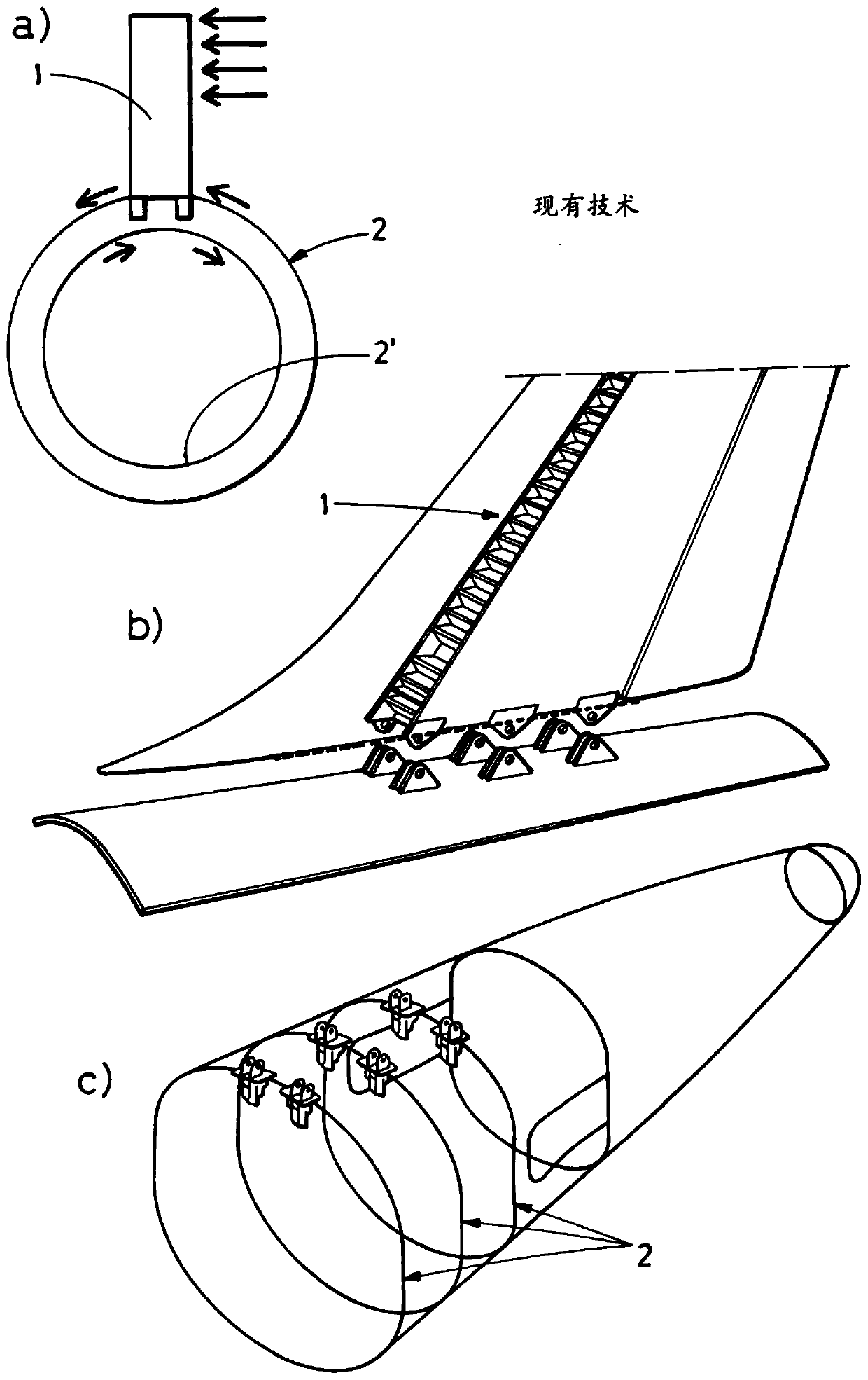
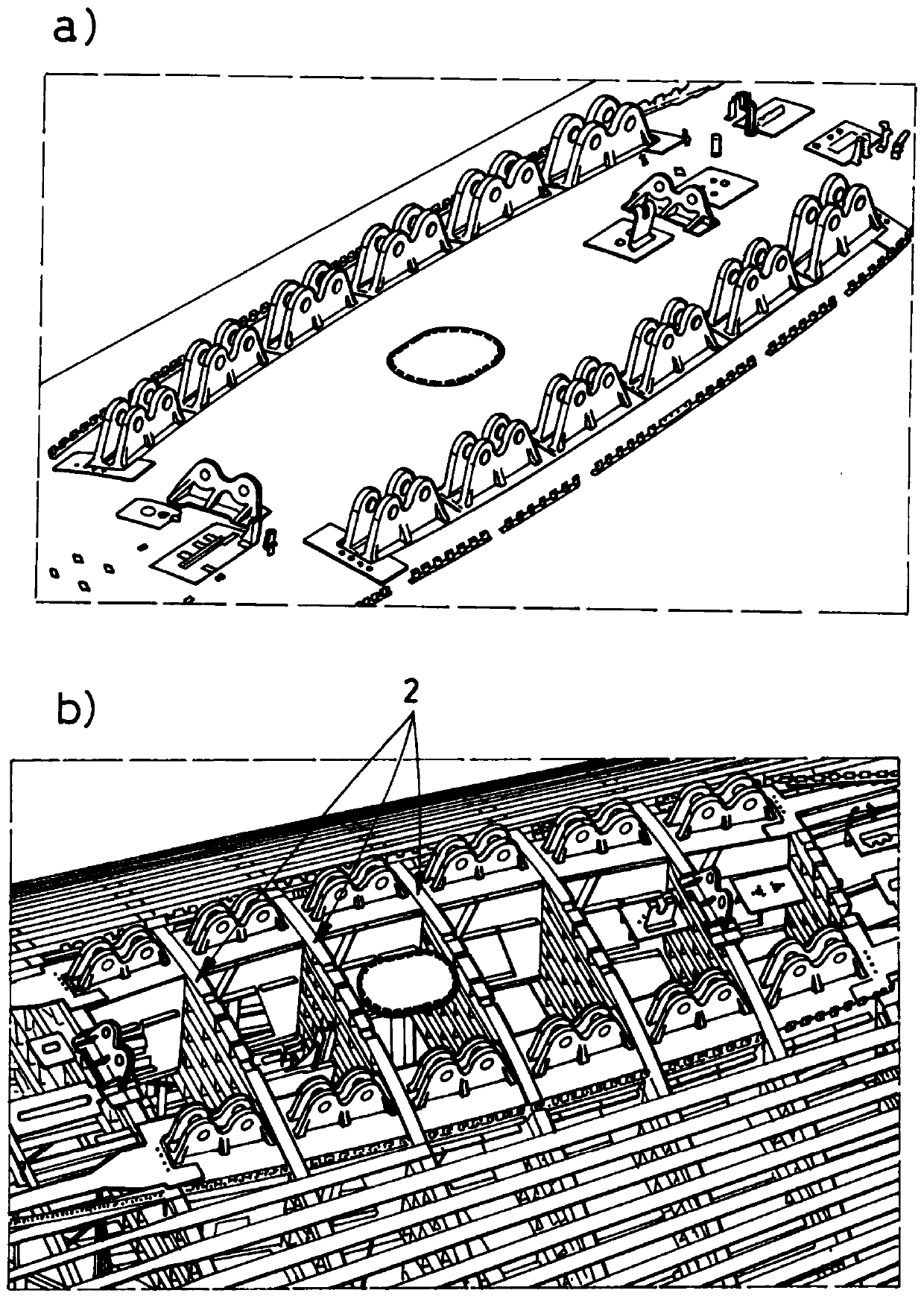
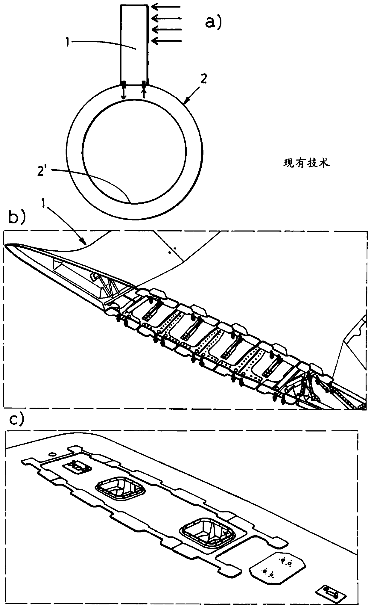
[0006] The main disadvantage common to both approaches is the high out-of-plane forces and stress concentrations in small areas in the skin of the fuselage and in the upper regions of the frame, which lead to very thick and heavy structural components, for example made of machined metal or high load frame made of forged metal

Method used


Image

  • Frame assembly for rear section of aircraft and rear section of aircraft
  • Frame assembly for rear section of aircraft and rear section of aircraft
  • Frame assembly for rear section of aircraft and rear section of aircraft

Examples


Embodiment Construction

[0029] Such as Figure 4 As depicted in, in the rear section of the aircraft, the vertical tail (1) has a plane of symmetry (4) and is operatively connected to serve as a beam and has two ends, for example by means of bolts, rivets or metal fittings. At least one support element (3) of the section (3'), wherein each of the ends (3') of the support element (3) is attached or clamped to the same frame (2), which also has The same symmetry plane of VTP (4). This symmetry plane (4) is a vertical symmetry plane, that is, when the aircraft is on the ground, the symmetry plane is perpendicular to the ground.

[0030] Each of the ends (3') when attached to the fuselage is in turn located on a different side of the plane of symmetry (4) of the vertical tail (1).

[0031] Preferably, according to Figure 4 to Figure 6 In the first embodiment depicted in, the support element (3) has a flat configuration, i.e. formed by a plate. According to the first embodiment, the end (3') is larger than...


PUM


Abstract

Provided are a frame assembly for a rear section of an aircraft and a rear section of an aircraft. The frame assembly comprises at least one frame (2) having a plane of symmetry (4), wherein the frameassembly also comprises at least one supporting element (3) having two ends (3'), wherein each one of the ends (3') is attached to said at least one frame (2) at different sides of the plane of symmetry (4).It permits a more effective transfer of loads coming from the vertical tail plane of the aircraft to the fuselage.

Description

Technical field [0001] The first aspect of the present invention relates to a frame assembly for the rear section of an aircraft for attaching a vertical tail (hereinafter referred to as VTP) to at least one frame of the rear section of the aircraft, the The frame components are used in the field of aviation technology, allowing the load from the VTP to be transferred to the fuselage more efficiently. A second aspect of the invention relates to an aircraft rear section including the frame assembly of the first aspect. Background technique [0002] Nowadays, considering any different ways for attaching the VTP to the fuselage of the aircraft, the load from the VTP is directly transferred to the upper part of the tail cone structure because this upper part is the area closest to the aforementioned VTP. Therefore, the main part of these loads ends up in a small area of ​​the skin and frame of the fuselage. [0003] There are two main ways to attach the VTP to the tail cone structure...

Claims


Application Information

Patent Timeline
Patent Type & Authority Applications(China)
IPC IPC(8): B64C1/06B64C5/06B64C1/12
CPCB64C1/061B64C5/06B64C1/12B64C1/26B64C1/065B64C1/064B64C5/02B64C1/0685
Inventor 马里亚·阿尔穆德纳·卡纳斯里奥斯杰西·哈维尔·瓦兹奎兹卡斯特罗弗朗奇斯科·乔斯·克鲁斯-多米格斯埃莱娜·阿雷瓦洛罗德里格斯努里亚·科梅纳雷霍马特利亚诺
Owner AIRBUS OPERATIONS SL
Learn More