
Electric brake booster

An electric braking and booster technology, applied in the directions of brakes, brake transmission devices, brake actuators, etc., can solve the problem of difficulty in ensuring clearance at the periphery, and achieve redundancy, facilitate layout configuration, and reduce failures. effect of possibility

Active Publication Date: 2020-05-22
HYUNDAI MOTOR CO LTD +1
View PDF14 Cites 0 Cited by
  • Summary
  • Abstract
  • Description
  • Claims
  • Application Information

AI Technical Summary

Problems solved by technology

As a result, there are problems because the installation position is limited, and it is difficult to secure clearance at the perimeter

Method used


Image

  • Electric brake booster
  • Electric brake booster
  • Electric brake booster

Examples


Embodiment Construction

[0034] Hereinafter, the present disclosure is described in detail with reference to the accompanying drawings. However, the present disclosure is not restricted or limited by the embodiments. The same reference numerals indicated in the various drawings refer to components performing substantially the same function.

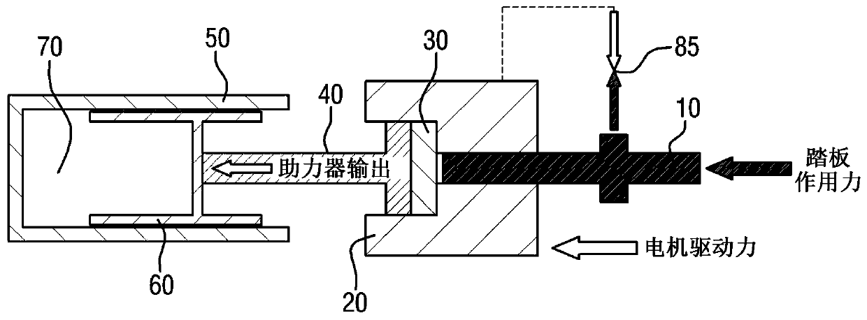
[0035] figure 1 is a view showing a state in which an electric booster in the related art operates.

[0036] refer to figure 1 , the electric booster in the prior art includes a pedal lever 10, which transmits the pedal force generated when the driver manipulates the brake pedal. The electric booster in the related art also includes a reaction disc 30 made of rubber material and deformed according to a force balance state between the booster body 20 and the pedal rod 10 . The prior art electric booster also includes a booster rod 40 that transmits the output of the booster to a piston 60 . The prior art electric booster also includes a chamber 50 defining a ...


PUM


Abstract

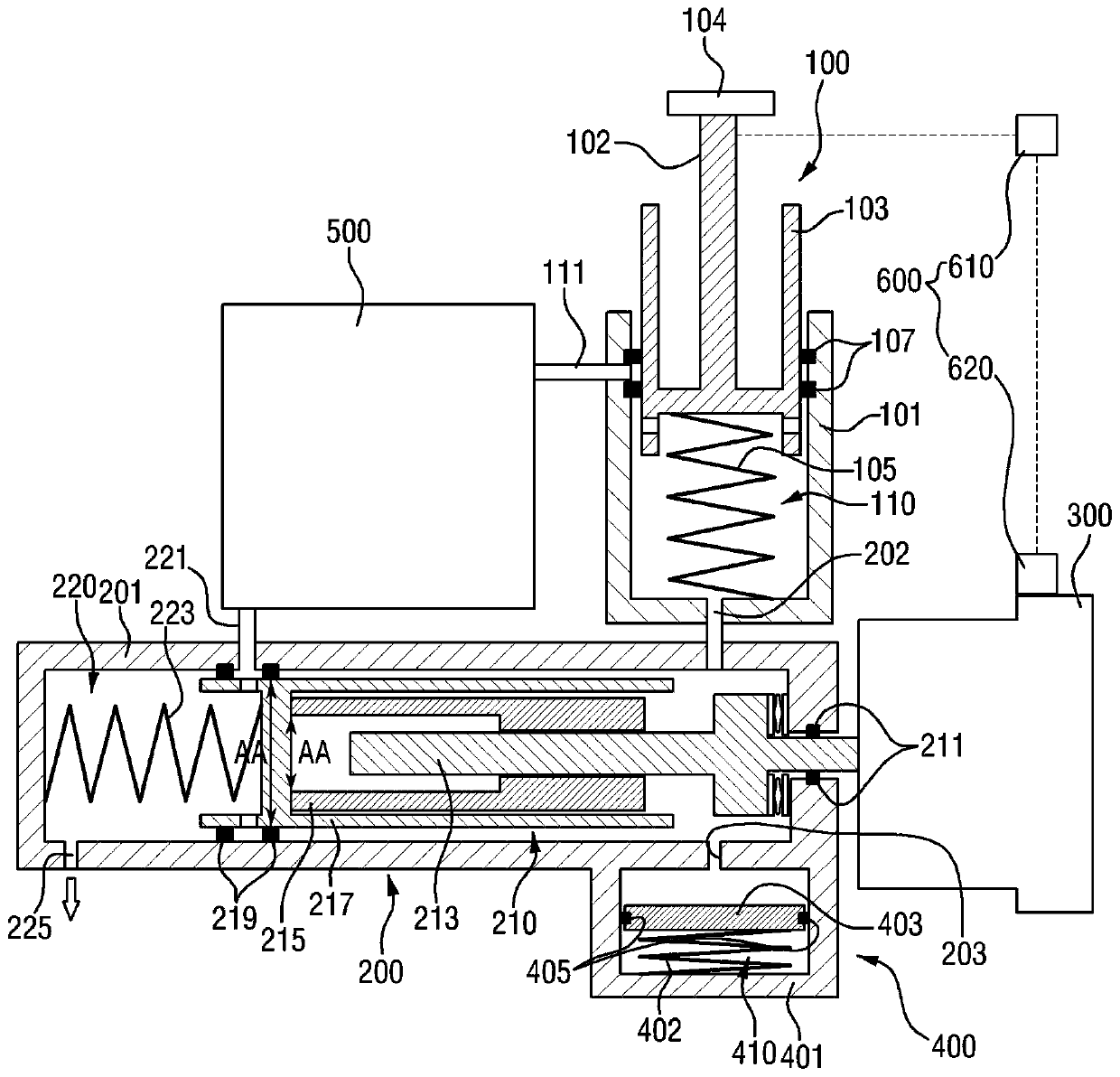
An electric brake booster includes: a first pressure device, which generates brake fluid pressure via manipulation of a brake pedal; a second pressure device, which is connected to the first pressuredevice through a flow path at one side of the second pressure device, receives brake fluid pressure from the first pressure device, and receives driving power of a motor connected to another side of the second pressure device; a sensing unit mounted in the motor and measuring a displacement of the brake pedal and a rotation angle of the motor; and a buffer device connected to the second pressure device and preventing an increase in pressure of the brake pedal when the motor does not operate, in which motor rotation is controlled with a displacement of the brake pedal.

Description

[0001] Cross References to Related Applications [0002] This application claims priority to Korean Patent Application No. 10-2018-0140267 filed with the Korean Intellectual Property Office on November 14, 2018, the disclosure of which is incorporated herein by reference in its entirety. technical field [0003] The present invention relates to an electric brake booster for a vehicle, and in particular to an electric brake booster which performs the function of a regulator for applying different brake pressures to the four wheels and boosts the A function of the brake pedal force generated when the brake pedal is applied. The electric brake booster also ensures redundancy of the actuators in preparation for the vehicle's autonomous driving. Background technique [0004] Typically, most vehicles are fitted with power-assisted braking devices such as power brakes, which allow the driver to slow down or stop the vehicle completely even if the driver presses down on the pedal w...

Claims


Application Information

Patent Timeline
Patent Type & Authority Applications(China)
IPC IPC(8): B60T13/74
CPCB60T13/745B60T13/146B60T13/403B60T13/58B60T13/66B60T7/042B60T8/17B60T13/662B60T2220/04F16D65/18B60T13/72F16D2121/24F16D2125/10
Inventor 李重熙车官亨田甲培黄世萝
Owner HYUNDAI MOTOR CO LTD
Learn More