
Strain theoretical value obtaining method and device based on finite element model

A finite element and theoretical value technology, applied in the field of aeronautical structure strength test, can solve the problems of inaccurate pasting position of strain gauge, difficulty between strain measurement value and theoretical value of strain, and non-existent pasting position.

Active Publication Date: 2020-05-19
XIAN AIRCRAFT DESIGN INST OF AVIATION IND OF CHINA
View PDF15 Cites 0 Cited by
  • Summary
  • Abstract
  • Description
  • Claims
  • Application Information

AI Technical Summary

Problems solved by technology

[0003] However, under normal circumstances, due to the inaccurate pasting position of the strain gauge, or the pasting position is not at the center of the finite element grid, the actual pasting position of the strain gauge is not completely consistent with the center point of the finite element grid
Therefore, this will bring great difficulties to the authenticity identification of the measured value of the strain gauge and the comparison between the measured value of the strain gauge and the theoretical value of the strain.

Method used


Image

  • Strain theoretical value obtaining method and device based on finite element model
  • Strain theoretical value obtaining method and device based on finite element model
  • Strain theoretical value obtaining method and device based on finite element model

Examples


Embodiment Construction

[0041] The present invention will be described in further detail below in conjunction with the accompanying drawings.

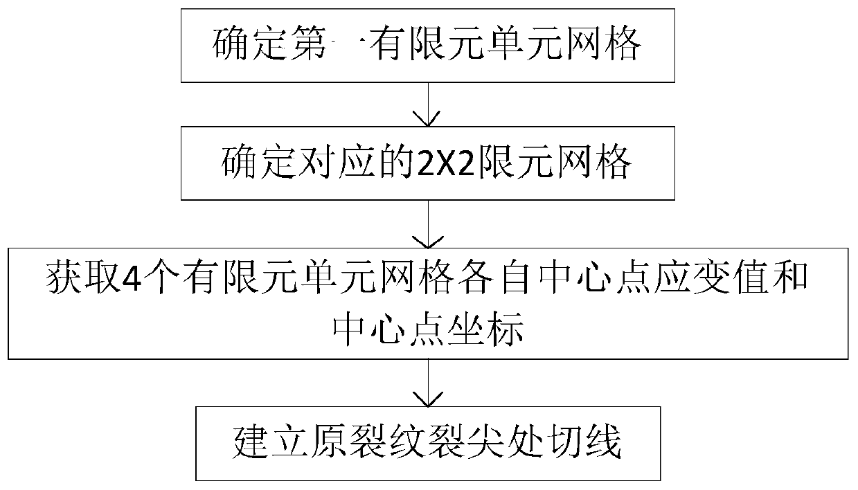
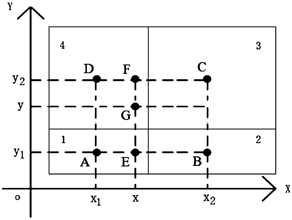
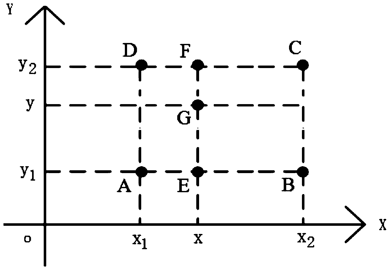
[0042] figure 1 A schematic flow chart of a method for obtaining theoretical strain values ​​based on a finite element model provided by the present invention, figure 2 is a schematic diagram of the theoretical acquisition method of the strain value at any position of the test piece based on the finite element model, image 3 is a schematic diagram of the strain calculation process, see Figure 2 to Figure 3 .

[0043] Such as figure 2 As shown, it is the minimum finite element grid required to apply the method of obtaining the theoretical strain value based on the finite element model, which consists of a 2×2 finite element grid. Must be contained in a 2 by 2 finite element mesh. The four finite element grid units are unit 1, unit 2, unit 3 and unit 4, and the center points of unit 1, unit 2, unit 3 and unit 4 are point A, point B, point C and point D...


PUM


Abstract

The invention provides a method and device for obtaining a strain theoretical value based on a finite element model. The method comprises the following steps: 1, determining a first finite element unit grid in the finite element model of a structural test part, and enabling the first finite element unit grid to be a grid pasted with a strain gauge; 2, in a structural test part finite element model, a 2 * 2 finite element grid corresponding to the first finite element unit grid is determined, and the 2 * 2 finite element grid comprises the first finite element unit grid; 3, obtaining respectivecentral point strain values and central point coordinates of the four finite element unit grids; and step 4, according to the respective central point strain values and central point coordinates of the four finite element unit grids, obtaining theoretical values corresponding to the strain gauges by adopting an interpolation algorithm. According to the method, the problem that theoretical calculation values of strain measurement points are not easy to obtain due to the fact that the strain measurement points of the test part are inconsistent with finite element grid calculation points is solved.

Description

technical field [0001] The invention belongs to the field of aeronautical structure strength tests, in particular to a method and device for obtaining theoretical strain values ​​based on finite element models. Background technique [0002] In the strength test of aircraft structure, it is usually necessary to establish a mechanical finite element model and conduct a preliminary stress analysis according to the structure and force characteristics of the structural test piece. According to the stress analysis results and test purpose, arrange and paste appropriate strain gauges on the structural surface of the structural test piece in advance, and verify by comparing the measured values ​​of these strain gauges with the theoretical strain values ​​at the center point of the finite element grid during the test The rationality of the force of the structural test piece. [0003] However, under normal circumstances, due to the inaccurate pasting position of the strain gauge, or ...

Claims


Application Information

Patent Timeline
IPC IPC(8): G06F30/15G06F30/23G06F119/14
Inventor 翟新康田小幸
Owner XIAN AIRCRAFT DESIGN INST OF AVIATION IND OF CHINA
Learn More