
Domestic electric appliance cabinet door sealing structure

A technology for sealing structures and household appliances, applied in sealing devices, door/window fittings, building structures, etc., can solve problems such as inconvenience for users, and achieve the effect of facilitating opening and improving adsorption capacity

Pending Publication Date: 2020-05-19
GREE ELECTRIC APPLIANCES INC
View PDF0 Cites 0 Cited by
  • Summary
  • Abstract
  • Description
  • Claims
  • Application Information

AI Technical Summary

Problems solved by technology

[0004] Therefore, the technical problem to be solved by the present invention is to overcome the defect that the cabinet door in the prior art is easy to bring inconvenience to the user.

Method used


Image

  • Domestic electric appliance cabinet door sealing structure
  • Domestic electric appliance cabinet door sealing structure
  • Domestic electric appliance cabinet door sealing structure

Examples


Embodiment 1

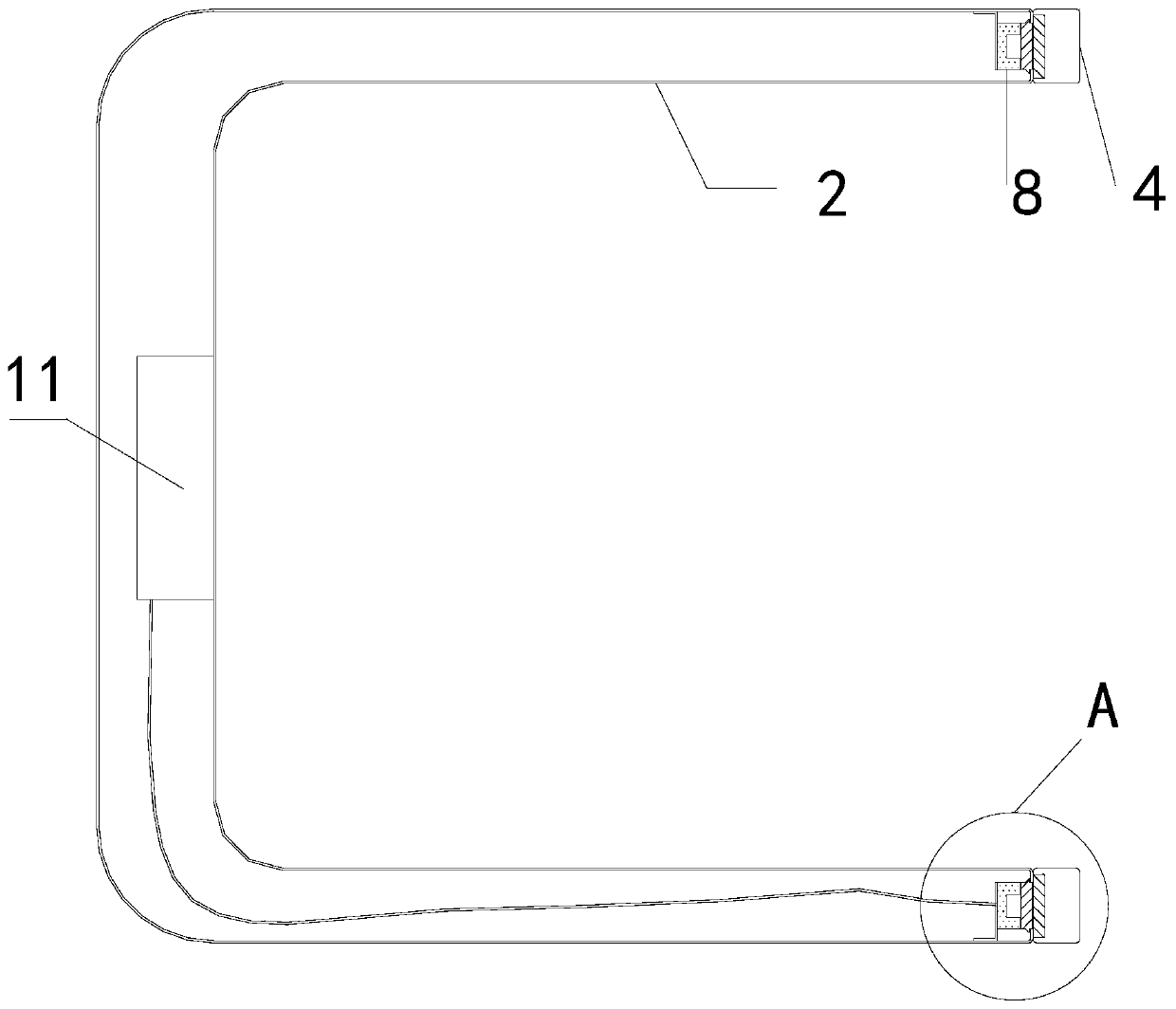
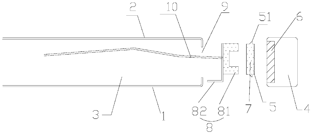
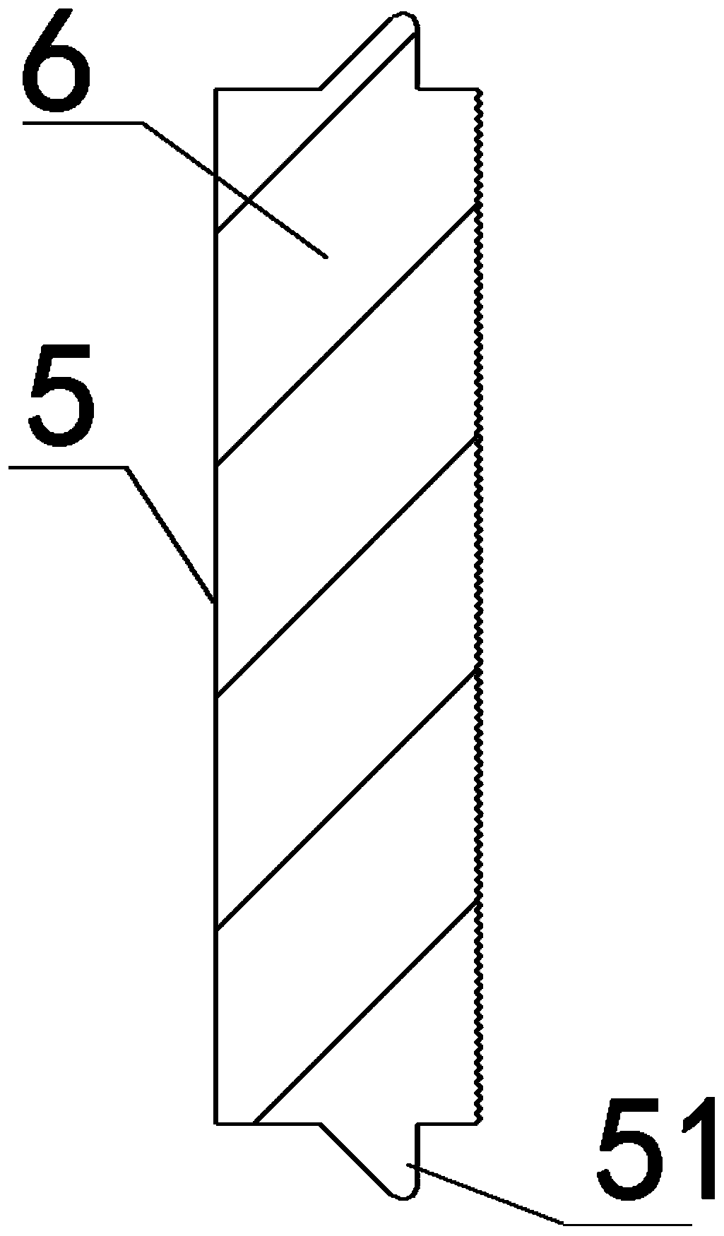
[0039] This embodiment provides a door sealing structure for household electrical appliances, including: a housing 1, an inner tank 2 arranged inside the housing 1, a sealing cavity 3 is formed between the housing 1 and the inner tank 2, The inner container 2 is used to place food materials that need to be processed; the cabinet door assembly 4 is arranged on the inner container 2 and is suitable for closing the housing 1; the sealing ring 5 is arranged in the sealed cavity 3, and the The sealing ring 5 is filled with magnetic fluid 6; the magnetizer 7 is arranged in the cabinet door assembly 4; the electromagnet assembly 8 is arranged opposite to the sealing ring 5 and is located in the sealing cavity 3, and the sealing ring 5 is arranged in the Between the electromagnet assembly 8 and the magnetic conductor 7, specifically, as figure 2 As shown, the sealing ring 5 is arranged on the right side of the electromagnet assembly 8 .

[0040] In this embodiment, there is no limit...

Embodiment 2

[0059] This embodiment is made on the basis of embodiment 1, as Figure 7 As shown, the magnetizer 7 itself is fixed in the sealed cavity 3 . Specifically, the magnetic conductor 7 can be directly connected to the sealing ring 5 . At this time, the electromagnet fixing seat 82 and the electromagnet 81 are arranged inside the cabinet door assembly 4 .

Embodiment 3

[0061] Such as Figure 8 As shown, in this embodiment, the sealing ring 5 is arranged in the cabinet door assembly 4, the magnetic conductor 7 is arranged in the sealed cavity, and the electromagnet assembly 8 is correspondingly arranged in the cabinet door assembly. The fixing method of the magnetizer inside the sealing cavity is not limited too much, it may be screw connection, glue fixing, or tension fit.

[0062] In this embodiment, a notch is provided on the cabinet door assembly for the sealing ring to protrude from, and the part of the sealing ring provided with the protruding structure acts on the magnetizer through the notch.


PUM


Abstract

The invention provides a domestic electric appliance cabinet door sealing structure. The sealing structure comprises a shell, a cabinet door assembly, a sealing ring, a magnetizer and an electromagnetassembly; an inner container is arranged on the inner side of the shell, and a sealing cavity is formed between the shell and the inner container; the cabinet door assembly is arranged on the inner container and is suitable for sealing the shell; the sealing ring is arranged on one of the sealing cavity and the cabinet door assembly, and the sealing ring is filled with magnetic fluid; the magnetizer is arranged on the other one of the sealing cavity and the cabinet door assembly; and the electromagnet assembly is arranged opposite to the sealing ring, and the sealing ring is arranged betweenthe electromagnet assembly and the magnetizer. The magnetic fluid serves as a magnetic conduction medium and can transmit magnetic force generated by the electromagnet assembly to the magnetizer, andat the moment, the sealing ring adsorbs the cabinet door assembly so that the cabinet door assembly cannot be freely opened; and when the cabinet door assembly needs to be opened, the electromagnet assembly is powered off, and at the moment, a user does not need to exert large force.

Description

technical field [0001] The invention relates to the technical field of the cabinet door of domestic electric appliances, in particular to a sealing structure of the cabinet door of domestic electric appliances. Background technique [0002] For many household electrical appliances, the cabinet door is an indispensable structure. By opening the cabinet door, the product to be processed is put into the corresponding household electrical appliance for processing. [0003] For different household electrical appliances, the role played by the cabinet door is also different. Dishwashers need to seal water and hot steam; steam ovens need to seal hot steam and high-temperature hot fluid; refrigerators need to seal cold fluid, etc. In the living appliances in the prior art, most cabinet doors themselves use rubber sealing rings Make a compression seal. The rubber sealing ring itself is susceptible to denaturation and even failure after being subjected to cold and heat shocks and co...

Claims


Application Information

Patent Timeline
Patent Type & Authority Applications(China)
IPC IPC(8): E06B7/16E06B7/23E05C19/16
CPCE06B7/16E06B7/23E05C19/166E05Y2900/30
Inventor 陈天佑贺平韦业军王青松
Owner GREE ELECTRIC APPLIANCES INC
Learn More