
Lower edge unfolding device of spreading machine with cloth pressing function

A cloth stretching machine and edge stripping technology, which is applied in the field of clothing machinery, can solve the problems such as the tightness of the edge stripping tooth belt and the influence of the edge stripping effect

Pending Publication Date: 2020-05-19
苏州比阳特服装设备有限公司
View PDF7 Cites 1 Cited by
  • Summary
  • Abstract
  • Description
  • Claims
  • Application Information

AI Technical Summary

Problems solved by technology

But this CN108557551A still has the following shortcoming: because cloth has certain flexibility and airtightness, thereby will wait for the cloth guide of edge stripping by cloth guide roller and make cloth edge pass stripping tooth belt (the patent claims " bottom stripping tooth belt"), it is often difficult to make the hemming area of ​​the fabric close to the stripping tooth belt, which seriously affects the stripping effect, especially the fabric with soft texture and severe hemming cannot meet the expectations of the industry after being stripped by the bottom stripping device

Method used


Image

  • Lower edge unfolding device of spreading machine with cloth pressing function
  • Lower edge unfolding device of spreading machine with cloth pressing function
  • Lower edge unfolding device of spreading machine with cloth pressing function

Examples


Embodiment Construction

[0022] In order to understand the technical essence and beneficial effects of the present invention more clearly, the applicant will describe in detail the following examples, but the descriptions of the examples are not intended to limit the solutions of the present invention. Equivalent transformations that are only formal but not substantive should be regarded as the scope of the technical solution of the present invention.

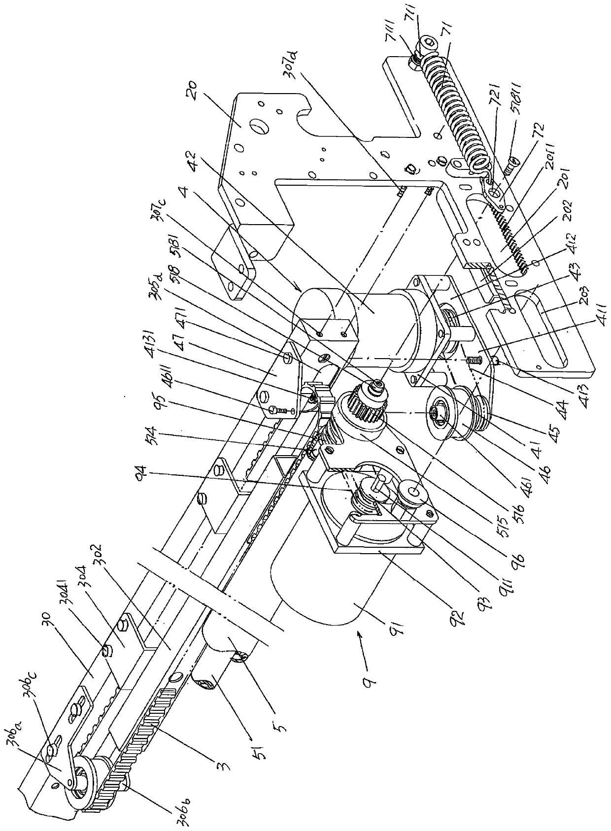
[0023] In the following descriptions, all concepts related to directionality or orientation of up, down, left, right, front and rear are based on figure 1 The current position is a reference, so it cannot be understood as a special limitation on the technical solution provided by the present invention.

[0024] See figure 1 , shows a cloth frame left wallboard 10, a cloth frame right wallboard 20 and a cloth frame 30, the cloth frame left wallboard 10 and the cloth frame right wallboard 20 form a face-to-face positional relationship that is Form a po...


PUM


Abstract

The invention discloses a lower edge unfolding device of a spreading machine with a cloth pressing function, and belongs to the technical field of clothing machinery. The lower edge unfolding device of the spreading machine with the cloth pressing function comprises a tenter left wallboard, a tenter right wallboard, a tenter, a left edge unfolding toothed belt, a left edge unfolding toothed belt driving mechanism, a right edge unfolding toothed belt and a right edge unfolding toothed belt driving mechanism, and is characterized by further comprising a cloth pressing roller, a cloth pressing roller shaft left tensioning and loosening mechanism, a cloth pressing roller shaft right tensioning and loosening mechanism, a chain reel driving mechanism and a cloth pressing roller driving mechanism. The cloth pressing roller is arranged on a cloth pressing roller supporting shaft, the cloth pressing roller shaft left tensioning and loosening mechanism is arranged on the left side of the left wallboard of the tenter, the cloth pressing roller shaft right tensioning and loosening mechanism is arranged on the right side of the right wallboard of the tenter, the chain reel driving mechanism isarranged on the right side of the front end of the left wallboard of the tenter, and the cloth pressing roller driving mechanism is arranged at the front end of the right wallboard. The hemming edgeson the two sides of cloth are fully unfolded and flattened, and the situation that subsequent processes are affected or even the cloth is scrapped is avoided.

Description

technical field [0001] The invention belongs to the technical field of garment machinery, and in particular relates to a lower edge stripping device of a cloth stretching machine with a cloth pressing function. Background technique [0002] The lower edge stripping device mentioned above is for the upper edge stripping device. The upper edge stripping device is set on both sides of the oblique position of the spreading machine in use, that is, at the corresponding two sides of the inclined position of the spreading machine. Each side is provided with an upper stripping device. For the concept of the oblique position, please refer to the Chinese patent CN102602729B mentioned below; the lower edge stripping device is arranged on both sides of the cloth breaking mechanism (also called "cloth cutting mechanism") corresponding to the cloth stretching machine in the use state. In view of the foregoing, the industry also refers to the upper edge stripping device as a primary edge ...

Claims


Application Information

Patent Timeline
IPC IPC(8): B65H23/02B65H20/02B65H47/00
CPCB65H20/02B65H23/02B65H47/00B65H2701/174
Inventor 徐建新
Owner 苏州比阳特服装设备有限公司
Learn More