Chip sorting and discharging device

A cutting and chip technology, used in transportation and packaging, conveyor objects, furnaces, etc., can solve problems such as low work efficiency and labor, and achieve high cutting efficiency, improve efficiency, and reduce labor efficiency.

Active Publication Date: 2020-05-19
云道图山东智能技术有限公司
View PDF7 Cites 1 Cited by
  • Summary
  • Abstract
  • Description
  • Claims
  • Application Information

AI Technical Summary

Problems solved by technology

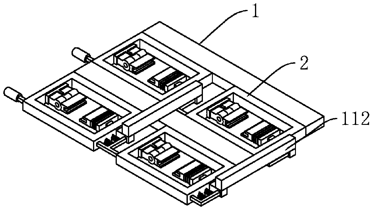
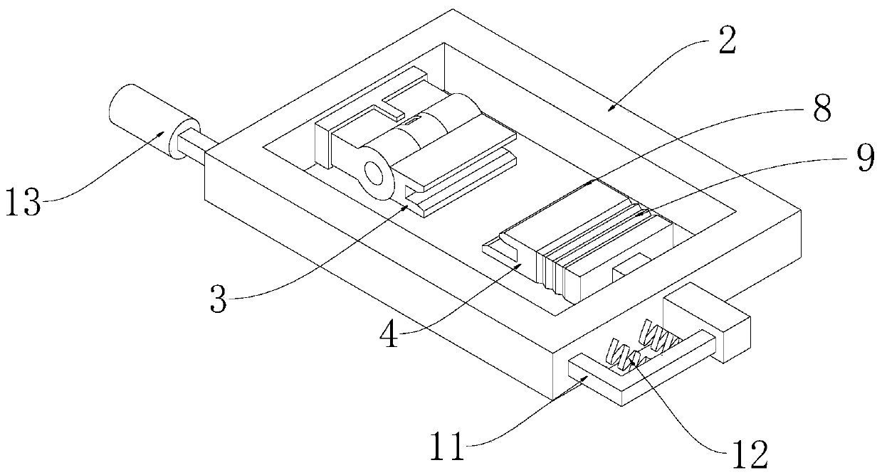
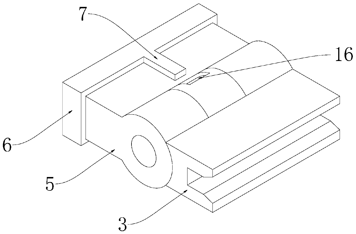
[0004] The purpose of the present invention is to solve the problem of low work efficiency in the common manual cutting method and low working efficiency after chip programming and sorting, and proposes a chip sorting and cutting device

Method used


Image

  • Chip sorting and discharging device
  • Chip sorting and discharging device
  • Chip sorting and discharging device

Examples


Embodiment Construction

[0022] The following will clearly and completely describe the technical solutions in the embodiments of the present invention with reference to the accompanying drawings in the embodiments of the present invention. Obviously, the described embodiments are only some, not all, embodiments of the present invention.

[0023] In describing the present invention, it should be understood that the terms "upper", "lower", "front", "rear", "left", "right", "top", "bottom", "inner", " The orientation or positional relationship indicated by "outside", etc. is based on the orientation or positional relationship shown in the drawings, and is only for the convenience of describing the present invention and simplifying the description, rather than indicating or implying that the referred device or element must have a specific orientation, so as to Specific orientation configurations and operations, therefore, are not to be construed as limitations on the invention.

[0024] refer to Figure ...


PUM


Abstract

The invention discloses a chip sorting and discharging device and belongs to the electric technical field. The chip sorting and discharging device comprises a connecting frame. Multiple frame bodies are arranged on the connecting frame. First clamping plates and second clamping plates are arranged on the frame bodies. One sides of sleeves are fixedly connected with one sides of the inner walls ofthe frames, and slopes are arranged on one sides of the second clamping plates. Rubber sleeves are arranged at one ends of the second clamping plates, second movable blocks are arranged at one ends ofthe rubber sleeves, and the outer portions of the second movable blocks are provided with transmission rods. By means of the chip sorting and discharging device, the first clamping plates and the second clamping plates can be used for clamping chips, the second movable blocks can be driven to move through the transmission rods, and therefore the second clamping plates can get away from the firstclamping plates, and the chips cannot be clamped; and under the effect of gravity, the chips can fall, the purpose of discharging is achieved, and the work efficiency of working personnel is improved.

Description

technical field [0001] The invention relates to the technical field of electric technology, in particular to a chip sorting and unloading device. Background technique [0002] The MCU in the chip is a single-chip microcomputer, which also includes various components such as resistors or capacitors to form a chip. The reverse side can be a metal terminal, a burning point, and the metal terminal is used to contact the device and communicate with it. For example, the chip is installed on the After the printer powder box, it can communicate with the printer. The burning point is a separately set point. It can contact the burning point through the burning device to carry out the burning program. The chip can only be programmed after the MCU is burned into the program. , to perform a certain function. [0003] After the chip is burned, it needs to be tested. After the test, the chip needs to be removed. The common way to remove it is to take it down one by one. The work efficienc...

Claims


Application Information

Patent Timeline
Patent Type & Authority Applications(China)
IPC IPC(8): B65G49/06B65G47/90
CPCB65G47/90B65G49/06
Inventor 周露露李立
Owner 云道图山东智能技术有限公司
Why Eureka
Try Eureka