Shearing part for plasticising screw

A technology of plasticizing screw and screw, which is applied in the direction of plastic recycling and recycling technology, can solve the problem of no macro homogenization operation, and achieve the effect of reducing risks

Active Publication Date: 2020-05-15
KRAUSSMAFFEI TECH GMBH
View PDF17 Cites 0 Cited by
  • Summary
  • Abstract
  • Description
  • Claims
  • Application Information

AI Technical Summary

Problems solved by technology

Thus, the previously agglomerated monofilaments, although present dispersedly after flowing through the shear, did not undergo macroscopic homogenization to compensate for large-scale concentration fluctuations

Method used


Image

  • Shearing part for plasticising screw
  • Shearing part for plasticising screw
  • Shearing part for plasticising screw

Examples


Embodiment Construction

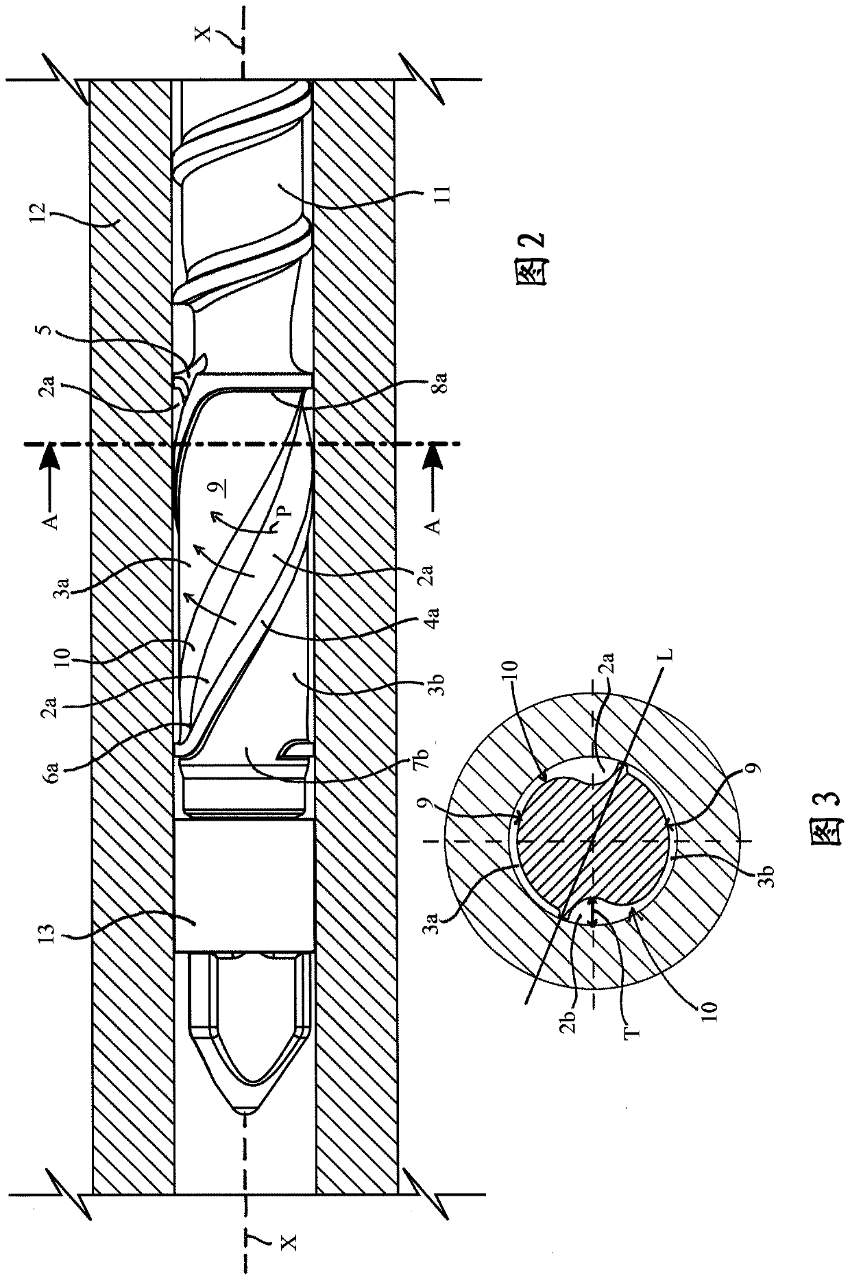
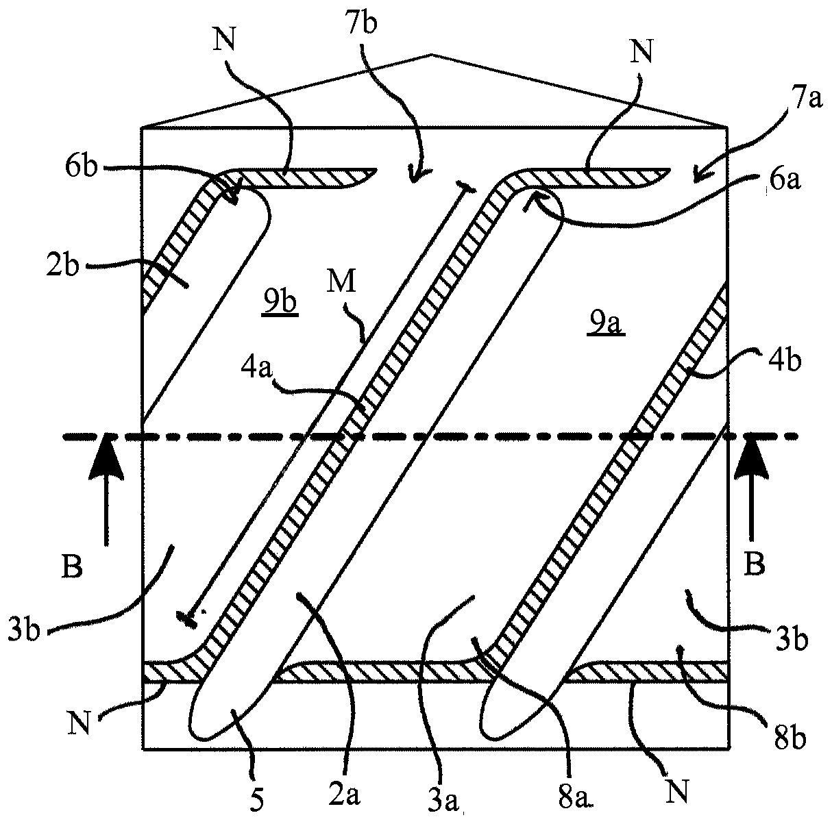
[0044] figure 2 The use of the shear element according to the invention is shown at the conveying downstream end of a screw 11 which is arranged rotatably and linearly drivably in a cylinder 12 . A non-reverse flow valve 13 is provided on the downstream side of the shearing piece. according to figure 2 and image 3 , the shearing element 1 according to the invention has two inlet channels 2a, 2b and two outlet channels 3a, 3b, which are respectively connected to each other in terms of flow and form each half of the shearing element 1, as in this case image 3 As indicated by the line L in the The two halves are arranged helically around the longitudinal axis X of the shear element 1 and are separated from one another in terms of flow by shut-off webs 4a, 4b. One half of the cutout is described in detail below. This half comprises an inlet channel 2 a and an outlet channel 3 a which extend helically around the longitudinal axis X of the shear element 1 . The inlet chann...


PUM


Abstract

The invention relates to a shearing part (1) for a plasticising screw. Th shearing part comprises at least one inlet channel (2, 2a, 2b) and at least one outlet channel (3, 3a, 3b) which run helicallyaround or parallel to the longitudinal axis (X) of the shearing part. The at least one inlet channel is open upstream and closed downstream, and the at least one outlet channel is open downstream andclosed upstream, wherein the inlet channel and the outlet channel are arranged directly adjacent and contiguous to one another, and are directly fluidically connected to one another such that the inflowing melt can flow directly from the inlet channel into the outlet channel, resulting in a flow direction running transversely to the longitudinal axis (X) of the shearing part. The at least one inlet channel has a depth (T) at which a shearing action on the melt is substantially avoided. The at least one outlet channel is designed as a shearing surface (9, 9a, 9b) such that a shearing action occurs on the melt flowing through the outlet channel.

Description

technical field [0001] The invention relates to a shear element for a screw of a plasticizing unit. Preferred fields of application are the processing of long-fiber granules (LFT granules) and the processing of dry blends consisting of chopped glass fibers and plastics. In both cases, the problem arises that there may be accumulations of fibers in the component. In LFT pellets, fiber build-up can be attributed to poor impregnation in the semi-finished product. When processing dry blends, the applied chopped glass fibers are compacted so that these chopped glass fibers are not forced inside the plasticizing unit. sexually dispersed In order to avoid such fiber accumulations (also referred to as fiber bundles), various embodiments of shear elements are known from the prior art. Background technique [0002] In so-called helical shears, the fibre-reinforced plastic melt passes through an inlet channel with a generally semicircular cross section, an overflow shear tab and th...

Claims


Application Information

Patent Timeline
Patent Type & Authority Applications(China)
IPC IPC(8): B29C48/64B29C48/395B29C48/505B29B7/40B29B7/42
CPCB29B7/401B29B7/421B29B7/429B29C48/397B29C48/56B29C48/575B29C48/2552B29C48/67B29C48/03B29C48/022B29K2105/12B29C48/68
Inventor M·沙德豪泽M·维特勒
Owner KRAUSSMAFFEI TECH GMBH
Why Eureka
Try Eureka