Dense splicing joint type concrete/ECC combined laminated plate and construction method thereof

A splicing joint and concrete technology, which is applied to floor slabs, climate change adaptation, building components, etc., can solve the problems of increased overall thickness of slabs, increased concrete consumption, waste of resources and construction costs, etc. The effect of increasing the ratio of tendons and reducing the occurrence of longitudinal splitting cracks

Inactive Publication Date: 2020-05-15
NANJING CONSTR ENG GRP +1
View PDF6 Cites 7 Cited by
  • Summary
  • Abstract
  • Description
  • Claims
  • Application Information

AI Technical Summary

Problems solved by technology

As a result, it is necessary to increase the thickness of the post-cast concrete on the floor to ensure the effective height of the floor at the joint, which wi

Method used


Image

  • Dense splicing joint type concrete/ECC combined laminated plate and construction method thereof
  • Dense splicing joint type concrete/ECC combined laminated plate and construction method thereof
  • Dense splicing joint type concrete/ECC combined laminated plate and construction method thereof

Examples


Embodiment 1

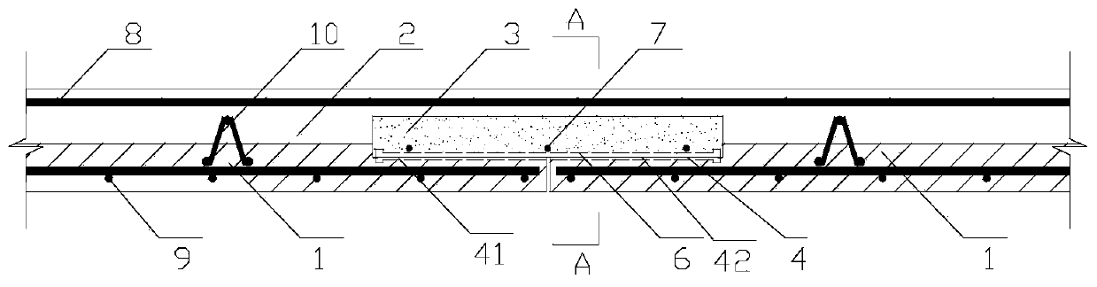
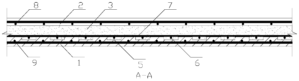
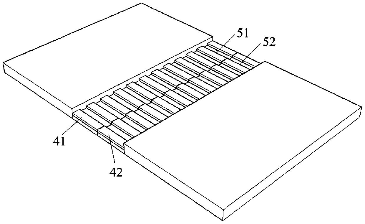
[0030] board-to-board connections such as Figure 1~2 : The prefabricated panel 1 has an L-shaped cross-section perpendicular to the joint direction, that is, groove one 41 and groove two 42 with openings at both ends, and two prefabricated bottom panels 1 are symmetrically spliced ​​to form a first groove 4 Structure. Groove 1 41 and groove 2 42 have a zigzag structure in the cross section parallel to the joint direction, that is, the upper surfaces of groove 1 41 and groove 2 42 of the prefabricated panel 1 are provided with concave grooves at intervals along the joint direction. Groove 3 51 and groove 4 52 form a zigzag surface, and groove 3 51 and groove 4 52 are aligned and spliced ​​to form the second groove 5 . The longitudinal rib 6 is connected to the bottom of the joint at the joint, and the two ends of the connecting longitudinal rib 6 have pier heads and are placed in the second groove 5 at the bottom of the first groove 4, and the additional full-length structura...


PUM

PropertyMeasurementUnit
Depthaaaaaaaaaa
Depthaaaaaaaaaa

Abstract

The invention discloses a dense splicing joint type concrete/ECC combined laminated plate and a construction method of the dense splicing joint type concrete/ECC combined laminated plate. The combinedlaminated plate comprises prefabricated plates and a cast-in-place layer. First grooves and second grooves are correspondingly formed in the two ends of the top of each prefabricated plate. Third grooves are formed in the bottoms of the first grooves at equal intervals in the direction perpendicular to the joint direction, fourth grooves are formed in the bottoms of the second grooves at equal intervals in the direction perpendicular to the joint direction, and the first grooves and the second grooves are formed in the direction parallel to the joint direction. After the prefabricated platesare symmetrically spliced, the first grooves and the second grooves are aligned to form first grooves, and the third grooves and the fourth grooves are aligned to form second grooves. Connecting longitudinal ribs are arranged in the second grooves. Additional long construction ribs are arranged at the bottoms of the first grooves. The first grooves and the second grooves are simultaneously pouredwith an ECC material. The construction method comprises the following steps that a die plate is assembled; and plate bottom carrying bars and truss rebars are bound, the prefabricated plates are poured, the prefabricated plates are hoisted in place, the connecting longitudinal ribs and the additional long construction ribs are bound, an ECC layer is poured, the plate top stress reinforcing ribs are bound, and the concrete layer is poured. By the adoption of the dense splicing joint type concrete/ECC combined laminated plate and the construction method, the normal use performance and the bearing capacity of the floor are ensured, meanwhile the thickness of the floor can be reduced, the consumption of the reinforcing bars and the dead weight of the floor are reduced, and the dense splicing joint type concrete/ECC combined laminated plate has the large economic benefits and is environmentally-friendly.

Description

technical field [0001] The invention relates to the field of concrete prefabricated structures, in particular to a close-jointed concrete / ECC combined laminated board and a construction method thereof. Background technique [0002] At present, prefabricated structures generally use truss reinforced concrete laminated slabs, in which prefabricated slabs are side-extruded, lapped at joints and post-cast concrete is the main method of two-way laminated slabs. This kind of two-way laminated slab steel reinforcement with direct lap joint of longitudinal reinforcement and joint of post-cast tape has reliable force transmission and good integrity. However, it is cumbersome to operate the prefabricated slab side formwork in the production process, and the ribbed part is easy to collide and bend during transportation. During the assembly process, the prefabricated slab needs to be precisely positioned and the formwork needs to be set up at the seam. Bring a series of difficulties an...

Claims


Application Information

Patent Timeline
IPC IPC(8): E04B5/17E04G21/00
CPCE04B5/17E04G21/00Y02A30/30
Inventor 姜国庆许荔罗时勇潘金龙
Owner NANJING CONSTR ENG GRP
Why Eureka
Try Eureka