
Tool changing oil cylinder mechanism and tool changing mechanism for machining center main shaft

A technology of oil cylinder and cylinder body, which is applied in the field of CNC machining center machine tool equipment, can solve the problems of spindle orientation deviation, slow spindle reset, short service life, etc., and achieve the effect of improving sealing effect, prolonging service life and long service life

Active Publication Date: 2020-05-15
GUANGZHOU HAOZHI ELECTROMECHANICAL
View PDF5 Cites 0 Cited by
  • Summary
  • Abstract
  • Description
  • Claims
  • Application Information

AI Technical Summary

Problems solved by technology

[0005] The second object of the present invention is to provide a tool change mechanism for the spindle of the machining center, which can solve the problems of oil leakage from the oil cylinder, slow reset of the spindle, orientation deviation of the spindle, tool drop, processing debris and dust on the handle of the tool, and long service life. Short and other technical issues

Method used


Image

  • Tool changing oil cylinder mechanism and tool changing mechanism for machining center main shaft
  • Tool changing oil cylinder mechanism and tool changing mechanism for machining center main shaft
  • Tool changing oil cylinder mechanism and tool changing mechanism for machining center main shaft

Examples


Embodiment Construction

[0029] Below, the present invention will be further described in conjunction with the accompanying drawings and specific implementation methods. It should be noted that, under the premise of not conflicting, the various embodiments described below or the technical features can be combined arbitrarily to form new embodiments. .

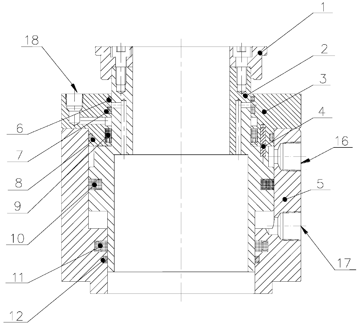
[0030] Such as figure 1 As shown, this embodiment discloses a tool change cylinder mechanism, including a cylinder body 5, a piston 2, a first guide ring 12, a top cover 1, a gland 3, an anti-rotation pin 4 and a sealing structure. cavity, the piston 2 is movably installed in the inner cavity, the first guide ring 12 is set between the piston 2 and the cylinder body 5, and is used to guide the piston 2 precisely, the top cover 1 is set on the piston 2, and the cylinder body 5 There are oil inlet 16 for unloading knife and air inlet 17 for broach. The oil inlet 16 for unloading knife and air inlet 17 for broach are respectively connected with the inner...


PUM


Abstract

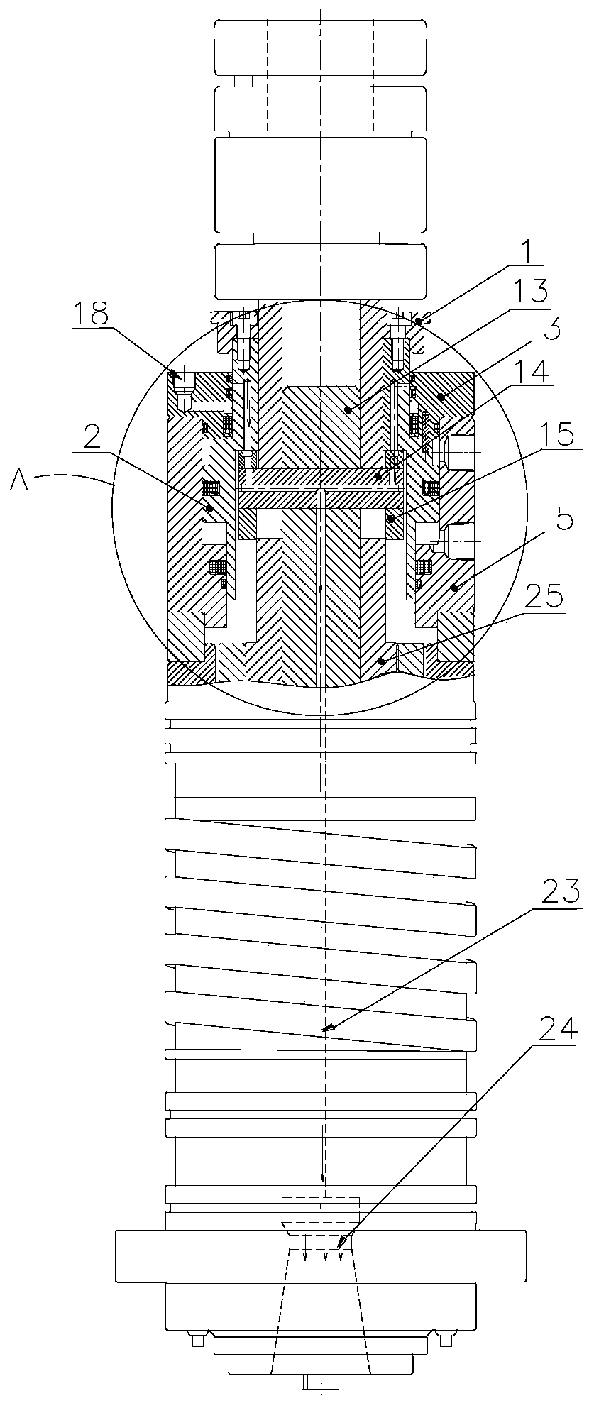
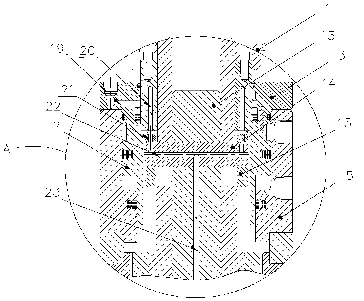
The invention discloses a tool changing oil cylinder mechanism. The tool changing oil cylinder mechanism comprises a cylinder body, a piston, a first guide ring, a top cover, a gland, an anti-rotationpin and a sealing structure, wherein the piston is movably mounted in an inner cavity of the cylinder body, the first guide ring is mounted between the piston and the cylinder body, the top cover ismounted on the piston, a tool unloading oil inlet and a tool clamping air inlet are formed in the cylinder body, the gland is mounted on the piston in a sleeving mode, the gland is located between thetop cover and the cylinder body, the gland is connected with the piston through the anti-rotation pin, and the sealing structure is mounted among the piston, the gland and the cylinder body. The invention further discloses a tool changing mechanism for a machining center main shaft. The tool changing mechanism comprises a shaft core, a tool clamping mechanism, the tool unclamping disc and the tool changing oil cylinder mechanism, wherein the tool changing oil cylinder mechanism is mounted on the shaft core, the tool clamping mechanism penetrates through the top cover, the piston and the shaftcore, the tool unclamping disc is mounted on the tool clamping mechanism in a sleeving mode and is matched with the piston, and a dust blowing ventilation pipeline is formed among the gland, the piston, the tool unclamping disc and the tool clamping mechanism. The tool changing mechanism can solve the technical problems such as oil leakage of an oil cylinder, slow return of the main shaft, directional offset of the main shaft, falling of a tool, dust accumulation of the tool, and short service life.

Description

technical field [0001] The invention relates to machine tool equipment of a numerically controlled machining center, in particular to a tool changing oil cylinder mechanism and a tool changing mechanism of a machining center spindle. Background technique [0002] CNC machining center machine tool is a kind of integration of mechanical equipment and CNC system. It is mainly used for industrial manufacturing processing, and is widely used in the processing of parts in aerospace, shipbuilding, automobile, mold, communication and other industries. Efficient automatic processing equipment suitable for complex parts. Its comprehensive processing ability has certain advantages. The workpiece can be clamped to complete multiple processes at one time, so it can effectively improve the processing accuracy and efficiency of parts. [0003] At present, the tool change mechanism of the spindle of the machining center is mainly through the input of hydraulic oil into the tool change cyli...

Claims


Application Information

Patent Timeline
Patent Type & Authority Applications(China)
IPC IPC(8): B23Q3/155B23Q11/00
CPCB23Q3/1552B23Q11/005
Inventor 黎训学麦光悦肖浩浩任明磊汤秀清
Owner GUANGZHOU HAOZHI ELECTROMECHANICAL
Learn More