
Square tube welding equipment

A technology for welding equipment and pipe materials, which is applied in the field of square pipe welding equipment, and can solve the problems of affecting the actual use effect of the equipment, reducing the accuracy of materials, and reducing precision.

Active Publication Date: 2020-05-15
WENLING SHUANGSEN STAINLESS STEEL
View PDF8 Cites 1 Cited by
  • Summary
  • Abstract
  • Description
  • Claims
  • Application Information

AI Technical Summary

Problems solved by technology

[0002] In the laser welding process, parts are often welded with high-heat laser, and there are many problems in the welding process. For example, in the process of pipe welding, it is often necessary to repeatedly place the pipe vertically before welding. Generally, Only manual placement is required in the bottom placement process, which cannot guarantee the verticality of the pipe processing. In some cases where precision is required, the use of manual placement will reduce the accuracy of pipe welding and reduce the efficiency of the welding process. The way of clamping and clamping is to manually adjust the locking mold, so that the pipe can be clamped efficiently, which increases the processing time of the personnel, and often adjusts the mold, which will also cause loosening of the relevant structure inside the mold. , so that the effect of pipe clamping is reduced, and the actual use effect of the equipment will be affected after a long time, so that the accuracy of the material processed by the equipment will be reduced

Method used


Image

  • Square tube welding equipment
  • Square tube welding equipment
  • Square tube welding equipment

Examples


Embodiment Construction

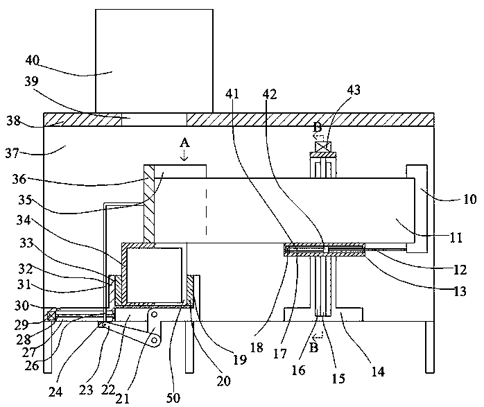
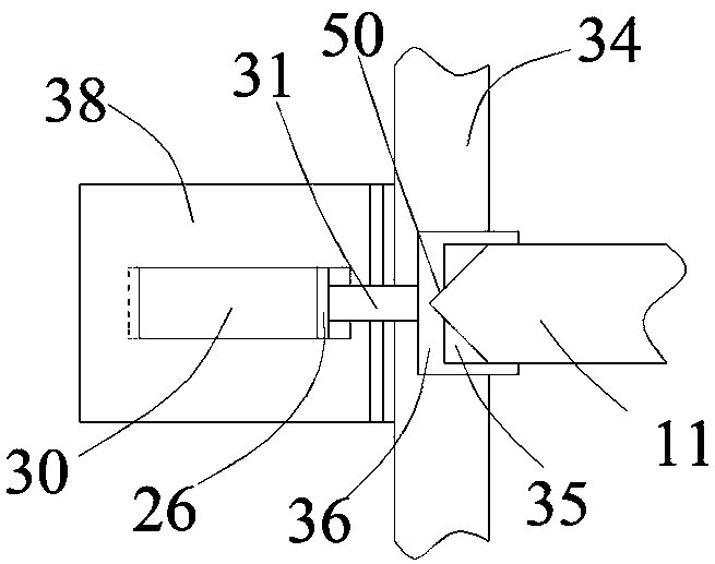
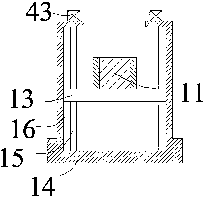
[0020] Such as Figure 1-Figure 3 As shown, the present invention is described in detail. For the convenience of description, the orientations mentioned below are now stipulated as follows: figure 1 The up, down, left, right, front and back directions of the projection relationship itself are consistent. A square pipe welding equipment of the present invention includes a support box 38, and an internal installation cavity 37 penetrating left and right is arranged in the support box 38. The upper end of the internal installation cavity 37 A penetrating inner cavity 39 is arranged in the wall, and a vertically placed bottom pipe 34 and top pipe 11 are arranged in the inner installation chamber 37, and an open clamping mating surface 50 is arranged in the bottom pipe 34. The snap-fit ​​surface 50 is a triangular opening, the bottom pipe 34 and the top pipe 11 are offset against each other, and the bottom pipe 34 is provided with a linkage placement device for placing the bottom p...


PUM


Abstract

The invention discloses square tube welding equipment. The square tube welding equipment comprises a supporting box body which is internally provided with an inner installation cavity through from left to right; a through inner cavity is formed in the upper end wall of the inner installation cavity in a communication mode; the inner installation cavity is internally provided with a bottom tube anda top tube perpendicular to the bottom tube; the bottom tube is internally provided with a clamping matched surface having an opening, the clamping matched surface is a triangular opening, the bottomtube abuts against the top tube, and the outer side of the bottom tube is provided with a linkage placement device used for conducting clamping linkage placement on the bottom tube; the equipment needs to driven an inner structure, the top tube is placed into the clamping matched surface, moreover, the top tube is completely flush with the bottom tube, and after a laser welding head works, the clamping matched surface is subjected to laser welding.

Description

technical field [0001] The invention relates to the technical field of pipe welding equipment, in particular to a square pipe welding equipment. Background technique [0002] In the laser welding process, parts are often welded with high-heat lasers. There are many problems in the welding process. For example, in the process of pipe welding, it is often necessary to repeatedly place the pipe vertically before welding. Generally, Only manual placement is required in the bottom placement process, which cannot guarantee the verticality of the pipe processing. In some cases where precision is required, the use of manual placement will reduce the accuracy of pipe welding and reduce the efficiency of the welding process. The way of clamping and clamping is to manually adjust the locking mold, so that the pipe can be clamped efficiently, which increases the processing time of the personnel, and often adjusts the mold, which will also cause loosening of the relevant structure inside...

Claims


Application Information

Patent Timeline
IPC IPC(8): B23K26/21B23K26/70B23K37/053B23K101/06
CPCB23K37/0533B23K26/21B23K26/702B23K2101/06
Inventor 王军
Owner WENLING SHUANGSEN STAINLESS STEEL
Learn More