
Long-strip-shaped steel plate straightening machine

A straightening machine and long strip technology, applied in the field of straightening machines, can solve the problems of complex structure and high cost of the straightening machine, and achieve the effects of simple structure, low cost and convenient operation

Inactive Publication Date: 2020-05-15
黄石三锐精密制造有限公司
View PDF0 Cites 0 Cited by
  • Summary
  • Abstract
  • Description
  • Claims
  • Application Information

AI Technical Summary

Problems solved by technology

[0003] The object of the present invention is to solve the problem of complex structure and high cost of the existing straightening machine, and provide a strip-shaped steel plate straightening machine, which is simple in structure and easy to operate, and is especially suitable for straightening strip-shaped steel plates

Method used


Image

  • Long-strip-shaped steel plate straightening machine
  • Long-strip-shaped steel plate straightening machine
  • Long-strip-shaped steel plate straightening machine

Examples


Embodiment Construction

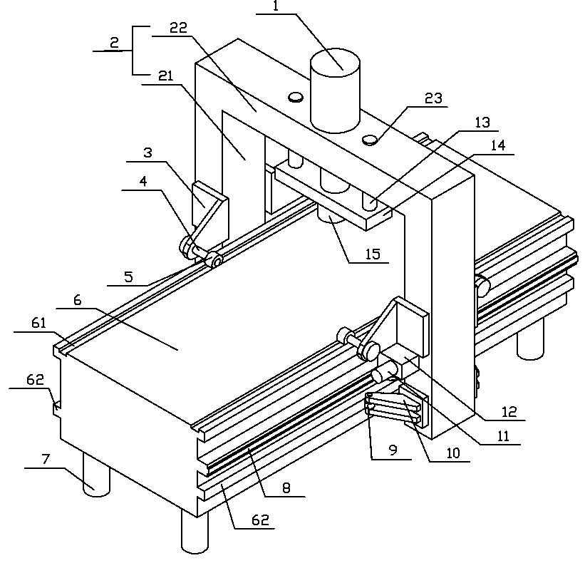
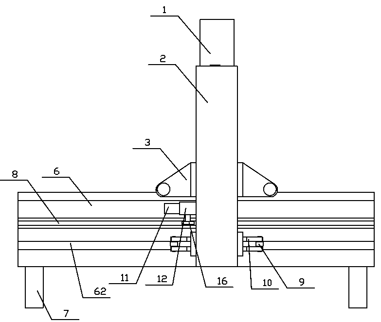
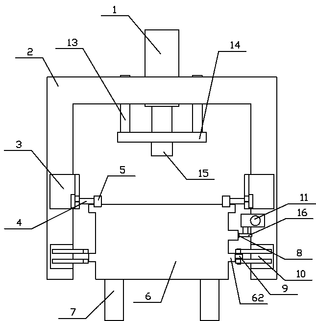
[0012] see Figure 1-3 , the present embodiment includes a rectangular workbench 6, the four corners of the bottom of the workbench 6 are equipped with feet 7, the top surface of the workbench 6 is a working plane, two grooves 61 are arranged on both sides of the top of the workbench 6, and the two grooves 61 are equipped with There is a gantry 2 that can move along the groove 61. A roller bracket 3 is installed on both sides of the two columns 21 of the gantry 2. Each roller bracket 3 is fixed with a wheel shaft 4, and the wheel shaft 4 extends to the workbench 6. And the end portion is equipped with roller 5 through bearing, and roller 5 rolls in groove 61, and oil cylinder 1 is housed in the middle of gantry 2 top crossbeam 22, and crossbeam 22 is positioned at oil cylinder 1 both sides and is provided with through hole 23, and straight line is housed in through hole 23 Bearing, the lower end of the piston rod of oil cylinder 1 is fixedly equipped with a connecting plate 14...


PUM


Abstract

The invention provides a long-strip-shaped steel plate straightening machine comprising a rectangular work table. Two grooves are formed in the two sides of the top of the work table. A portal frame capable of moving along the grooves is installed in the two grooves. Rolling wheel supports are installed on the two sides of each of two stand columns of the portal frame correspondingly. An axle is fixedly installed on each rolling wheel support. The axles extend to the work table. A rolling wheel is installed on the end portion of each axle through a bearing. The rolling wheels roll in the grooves. An oil cylinder is installed in the middle of a transvers beam on the top of the portal frame. Through holes are formed in the portions, located on the two sides of the oil cylinder, of the transverse beam. A linear bearing is installed in each through hole. A connection plate is fixedly installed at the lower end of a piston rod of the oil cylinder. Two guide columns are fixedly installed atthe two ends of the connection plate. The upper ends of the guide columns are installed in the linear bearings. A pressing head is installed at the position, located on the position rod, of the bottomof the connection plate. A rack is installed on a side face of the work table along the total length. A motor and a speed reducer are fixedly installed on the stand column, corresponding to the rack,of the portal frame. A gear meshed with the rack is installed at the output end of the speed reducer. The long-strip-shaped steel plate straightening machine is simple in structure, low in cost and convenient to operate.

Description

technical field [0001] The invention relates to the technical field of straightening machines, in particular to a strip-shaped steel plate straightening machine. Background technique [0002] During the bending process of the bending machine, the bottom of the slider will produce upward disturbance deformation. In order to improve the bending accuracy, the workbench under the slider is designed as a compensation mechanism that can compensate for this deformation. The compensation mechanism needs to use straightness. Therefore, in the process of making the compensation mechanism, a straightening machine must be used to straighten the long steel plate; the existing straightening machine has a complex structure and high cost. Contents of the invention [0003] The object of the present invention is to solve the problem of complex structure and high cost of the existing straightening machine, and provide a strip-shaped steel plate straightening machine, which has a simple stru...

Claims


Application Information

Patent Timeline
Patent Type & Authority Applications(China)
IPC IPC(8): B21D1/06
CPCB21D1/06
Inventor 郑正军徐林
Owner 黄石三锐精密制造有限公司
Learn More