
Micro-pressure filtering device in front of pump

A filter device, a technology in front of a pump, applied in the directions of filtration separation, filtration circuit, fixed filter element filter, etc., can solve the problems of high cost and energy consumption, consuming human resources, low filtration efficiency, etc., and achieves convenient and quick disassembly and assembly, Improve filtration efficiency and good filtration effect

Pending Publication Date: 2020-05-15
XINJIANG AGRI UNIV
View PDF0 Cites 1 Cited by
  • Summary
  • Abstract
  • Description
  • Claims
  • Application Information

AI Technical Summary

Problems solved by technology

[0004] The purpose of this application is to provide a pre-pump micro-pressure filter device, which overcomes the above-mentioned deficiencies in the prior art, and can effectively solve the problems of labor-intensive, easy-to-block, and low-filtration efficiency of the existing water-saving irrigation pump pre-filter devices. , high cost and energy consumption

Method used


Image

  • Micro-pressure filtering device in front of pump
  • Micro-pressure filtering device in front of pump
  • Micro-pressure filtering device in front of pump

Examples


Embodiment 1

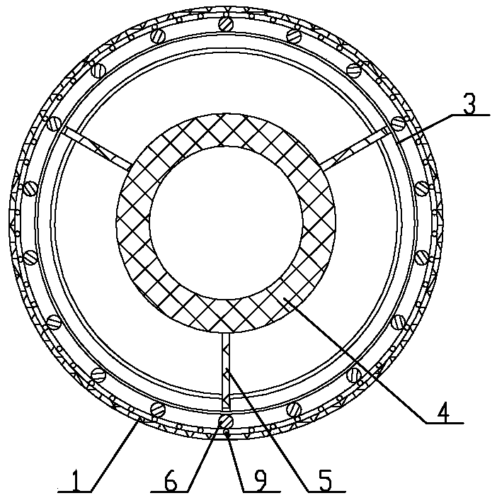
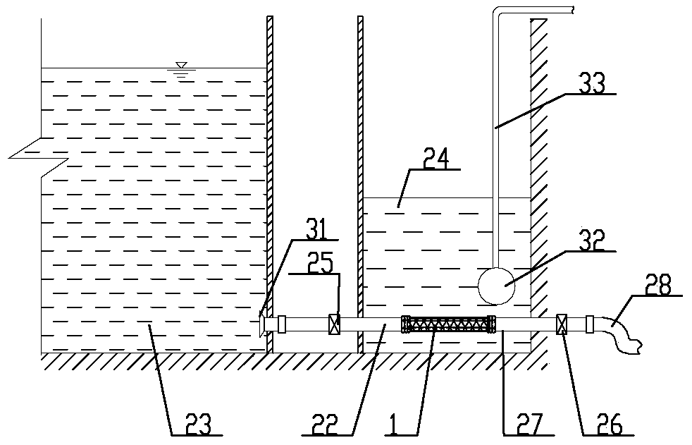
[0022] Embodiment 1: as figure 1 As shown in -3, the micro-pressure filter device in front of the pump includes a filter screen cylinder 1, a left joint, a right joint, a left water distribution seat 2, a right water distribution seat 3 and a water separator, and the filter screen cylinder 1 is arranged horizontally along the axis Horizontal cylindrical cylinder, the left end of the filter cylinder 1 is fixed with a left joint that can be connected to the left water inlet pipeline, the right end of the filter cylinder 1 is fixed with a right joint that can be connected with the right sewage pipeline, the left joint or the filter cylinder 1 The center of the inner cavity at the left end is fixed with the left water distributor 2, and the center of the inner cavity at the right end of the right joint or filter cylinder 1 is fixed with the right water distributor 3, and the water distributor is installed through the left water distributor 2 and the right water distributor 3 In th...

Embodiment 2

[0031] Embodiment 2: as Figure 4 As shown, a filter housing 29 is installed on the outside of the filter screen cylinder 1, and the inside of the filter housing 29 has a filter chamber surrounding the filter screen cylinder 1. The left part of the filter housing 29 is equipped with a left joint, and the filter housing The right part of the body 29 is equipped with a right joint, and the filter screen cylinder 1 isolates the inner chamber of the left joint and the inner chamber of the right joint from the filter cavity, and the bottom of the filter housing 29 is provided with a water supply port 30, and the water supply port 30 The cavity is connected with the filter chamber, and the left joint includes a joint body 10 and a pipe connection screw sleeve 12. An external groove 13 with a joint external thread is arranged on the left side of the joint body 10, and the pipe connection screw sleeve 12 passes through the outside of the joint. The thread is fixedly installed in the e...


PUM


Abstract

The invention relates to the technical field of water-saving irrigation filtering devices, in particular to a micro-pressure filtering device in front of a pump. The device comprises a filter screen cylinder, a left joint, a right joint, a left water distribution seat, a right water distribution seat and a water distributor. The filter screen cylinder is a transverse cylinder of which the axis ishorizontally arranged, and the left joint capable of being connected with a left water inlet pipeline is fixed at the left end of the filter screen cylinder. The device is reasonable and compact in structure and convenient to use. The water distributor arranged in the filter screen cylinder can effectively improve the flow velocity of water flow near the filter screen. The inner wall of the filterscreen cylinder can be scoured and cleaned by opening a pipeline or a valve connected with the right joint. Mesh blockage can be avoided, filter cake formation can be prevented, the filtering area isincreased, the filtering capacity is effectively improved, the filtering efficiency is remarkably improved, filtering is not influenced during pollution discharge, and uninterrupted water supply canbe realized. The filtering device has the characteristics of good filtering effect, remarkable reduction of energy consumption, energy conservation, convenience and quickness in disassembly and assembly, easiness in cleaning and easiness in operation.

Description

technical field [0001] The application relates to the technical field of water-saving irrigation filter devices, and is a micro-pressure filter device before a pump. Background technique [0002] my country's water resources are relatively poor, especially in western regions such as Xinjiang and Gansu, where water resources are scarce, precipitation is scarce, and evaporation is strong. The contradiction between water resource shortage and economic development is becoming increasingly prominent. Drought and water shortage have seriously affected my country's industrial production. Agricultural Development. Micro-irrigation engineering technology plays an important role in efficient water saving. How to effectively use surface water from mountain streams for micro-irrigation has become the key to popularize efficient water-saving technology. However, due to the high sediment content of irrigation water sources 1. The problem of large particle size of sediment can easily cause...

Claims


Application Information

Patent Timeline
Patent Type & Authority Applications(China)
IPC IPC(8): B01D29/23B01D29/66B01D29/90B01D29/96B01D36/04
CPCB01D29/23B01D29/66B01D29/904B01D29/902B01D29/96B01D36/04
Inventor 陶洪飞周洋李巧马合木江·艾合买提杨文新姜有为魏建群
Owner XINJIANG AGRI UNIV
Learn More