Wireless smooth ring for rotating mechanism

A smooth ring, wireless technology, applied in the field of slip rings, can solve the problems of rising cost of the whole machine, failure of optical fiber slip rings, high cost, etc., and achieve the effect of reducing alignment accuracy, compact structure design, and compact installation space

Pending Publication Date: 2020-05-12
SHANDONG INST OF AEROSPACE ELECTRONICS TECH
View PDF2 Cites 1 Cited by
  • Summary
  • Abstract
  • Description
  • Claims
  • Application Information

AI Technical Summary

Problems solved by technology

If there is a loose misalignment, it will cause the optical fiber slip ring to be subjected to lateral force and cause failure
In addition, the cost of this kind of slip ring is very high due to high-precision manufacturing and assembly requirements, resulting in an increase in the cost of the whole machine

Method used


Image

  • Wireless smooth ring for rotating mechanism
  • Wireless smooth ring for rotating mechanism
  • Wireless smooth ring for rotating mechanism

Examples


Embodiment Construction

[0028] In order to make the purpose, technical solutions and advantages of the present invention clearer, the present invention will be described in further detail below in conjunction with the accompanying drawings.

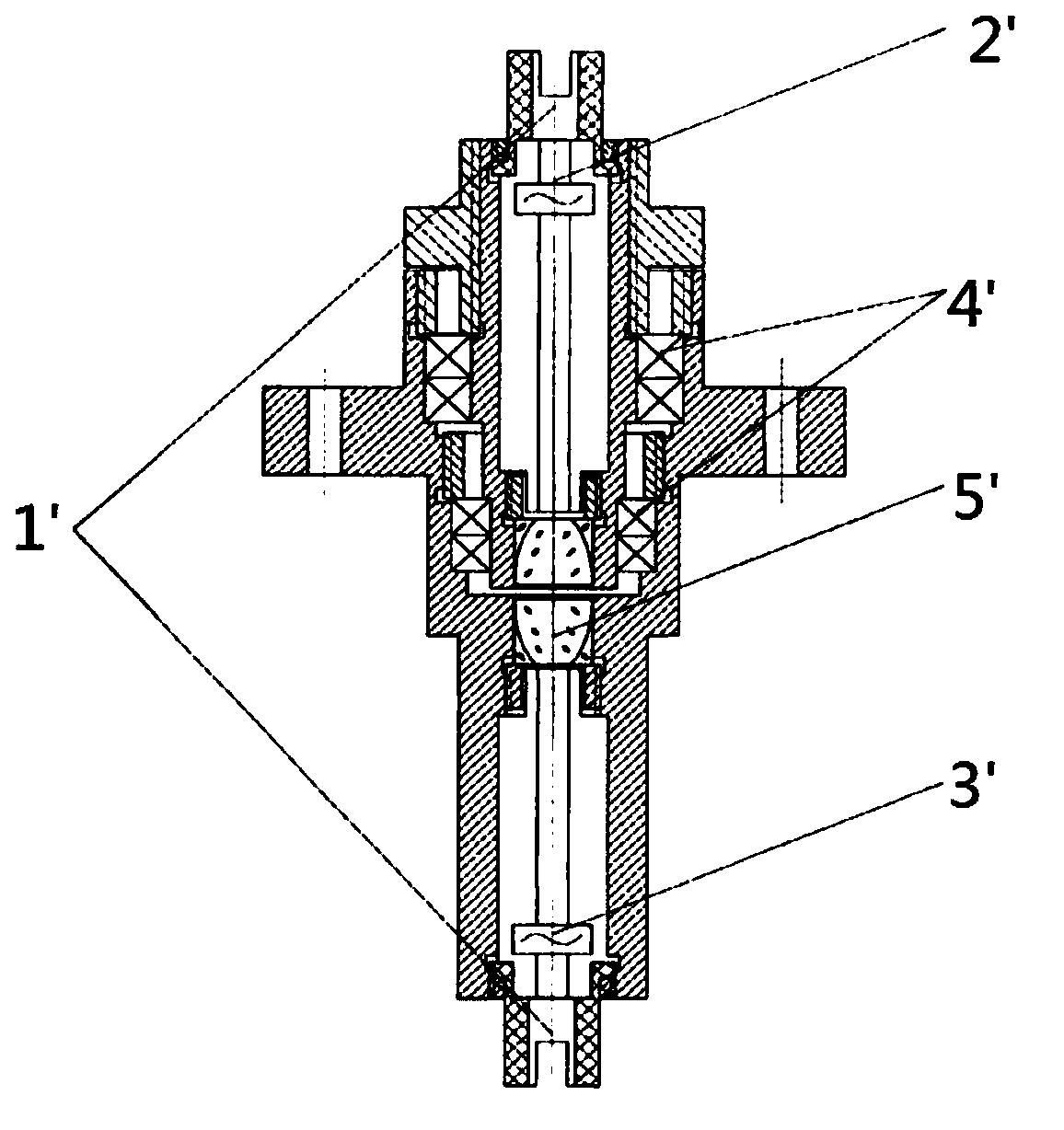
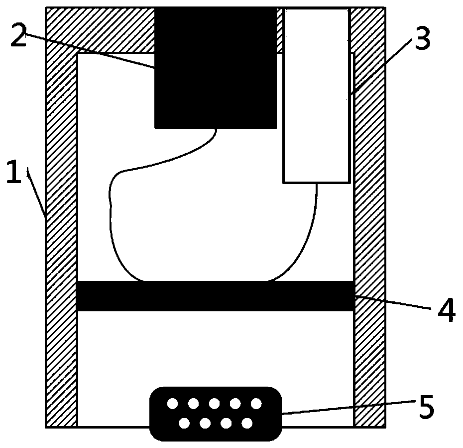
[0029] Such as figure 2 Shown, a kind of wireless smooth ring that is used for rotating mechanism, comprises the mechanical shell of cavity cylindrical shape, is fixed in the signal transmitting mechanism and signal receiving mechanism and circuit board, external connector in the mechanism shell; Said signal transmitting mechanism and The signal receiving mechanism is connected with the circuit board through an optical fiber; the circuit board includes a signal transmitting circuit and a signal receiving circuit; the external connector is used for power supply and data transmission and reception of the slip ring.

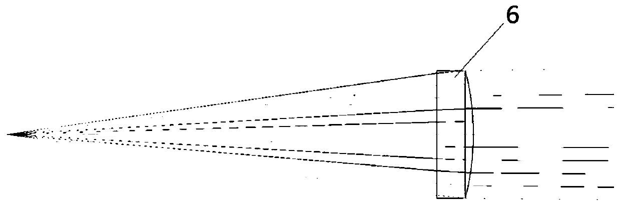
[0030] Such as image 3 , 4 As shown, the signal transmitting mechanism includes a first convex lens through which the optical signal converted by...


PUM


Abstract

The invention relates to a wireless smooth ring for a rotating mechanism. The wireless smooth ring comprises a mechanical shell with a cylindrical cavity, a signal transmitting mechanism, a signal receiving mechanism, a circuit board and an external connector, wherein the signal transmitting mechanism and the signal receiving mechanism are fixed in the mechanical shell; the signal transmitting mechanism and the signal receiving mechanism are connected with the circuit board through optical fibers; the circuit board comprises a signal transmitting circuit and a signal receiving circuit; the external connector is used for supplying power to the slip ring and transmitting and receiving data; a wireless non-contact laser communication mode is adopted for signal transmitting and receiving. Thebeneficial effects of the invention are that the wireless smooth ring is longer in service life and higher in transmission rate; higher transmission speed and lower processing precision requirements are realized; and the lower assembly requirement and the lower machining requirement are achieved.

Description

technical field [0001] The invention belongs to the technical field of slip rings, in particular to a wireless slip ring used for a rotating mechanism. Background technique [0002] In some rotating structures, the signal cannot be transmitted by wires due to the rotational movement, and a conductive slip ring is required to complete the signal transmission. Conductive slip rings are widely used in robotics, wind power generation and military fields, such as industrial manipulators, military satellite tracking, medical equipment scanning systems, aerospace vehicle tracking systems, etc. Due to the high-speed friction between the inner and outer rings, the contact conductive slip ring will generate heat and noise, and it will be easily deformed after a long time, affecting the tightness of the contact, thereby affecting the contact resistance of the slip ring, resulting in distortion of the transmission signal; at the same time, the wear is also reduced. The service life of ...

Claims


Application Information

Patent Timeline
Patent Type & Authority Applications(China)
IPC IPC(8): H04B10/40G02B19/00
CPCH04B10/40G02B19/0014G02B19/0085
Inventor 于方磊王健隆吴世臣孟祥翔曲志超石德乐肖军强李兰民
Owner SHANDONG INST OF AEROSPACE ELECTRONICS TECH
Why Eureka
Try Eureka