
Three-dimensional building model demonstration device and demonstration method

A technology of architectural models and demonstration devices, applied to teaching models, educational tools, instruments, etc., can solve the problems of difficult demonstration operation, not intuitive enough, complex structure of demonstration devices, etc., and achieve convenient and quick demonstration, simple structure and smooth passage Effect

Inactive Publication Date: 2020-05-12
孙道明
View PDF7 Cites 0 Cited by
  • Summary
  • Abstract
  • Description
  • Claims
  • Application Information

AI Technical Summary

Problems solved by technology

[0002] Existing 3D architectural model demonstration devices generally make multiple building components, and build a 3D model by plugging the building components themselves. This kind of 3D architectural model demonstration device has a complex structure, and the demonstration operation is relatively difficult, and it is not intuitive enough.

Method used


Image

  • Three-dimensional building model demonstration device and demonstration method
  • Three-dimensional building model demonstration device and demonstration method
  • Three-dimensional building model demonstration device and demonstration method

Examples


example 1

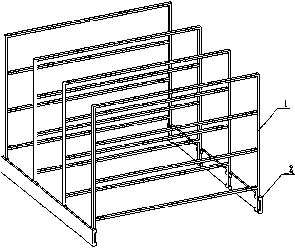
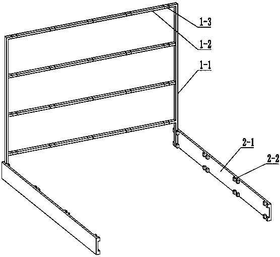
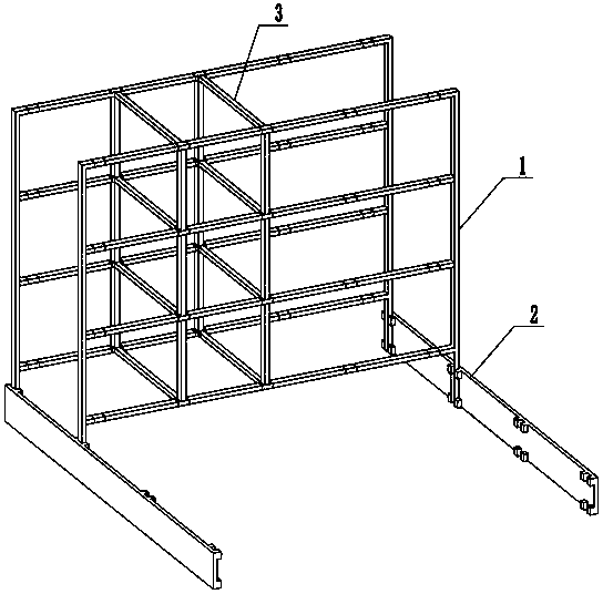
[0018] Such as Figure 1-Figure 3 The three-dimensional architectural model demonstration device shown includes a support 2 , four mesh sheets 1 and a plurality of demonstration poles 3 . The support 2 includes two vertical boards 2-1 arranged in parallel, each vertical board 2-1 is provided with multiple vertical connecting grooves 2-2 on the side adjacent to the other vertical board 2-1, each The connection groove 2-2 includes two groove bodies protruding from the vertical plate 2-1, each connection groove 2-2 is provided with a card opening on the surface facing the adjacent vertical plate 2-1, and each connection groove A magnet is embedded in the groove wall. The mesh 1 includes two vertical bars 1-1 and four cross bars 1-2 whose two ends are respectively fixed on the two vertical bars 1-1, and each cross bar 1-2 is provided with four identical and alternate Separated marking areas 1-3, adjacent marking areas 1-3 are equally spaced, magnets are arranged in the marking a...

example 2

[0021] The difference between Example 2 and Example 1 is that the vertical bars 1-1 in Example 2 all adopt telescopic rod bodies, and the vertical bars 1-1 are all length-adjustable rod bodies between every two horizontal bars 1-2. When the vertical bar 1-1 is pulled to the longest state, the gap between the adjacent two horizontal bars 1-2 is N, which can ensure that the cubic space can be built, and the vertical bar 1-1 can be compressed to the shortest when it is carried, for example For carrying, it can also be adjusted according to the floor height when demonstrating different floor heights. When the gap between two adjacent cross bars 1-2 is adjusted to not be N, there is no need to take a demonstration bar body vertically.

[0022] Other structures and demonstration methods of Example 2 are the same as Example 1.


PUM


Abstract

The invention discloses a three-dimensional building model demonstration device and a demonstration method. All transverse rods are arranged in multiple layers; a plurality of transverse rods are arranged on each layer; the intervals between every two adjacent transverse rods in the horizontal direction and the vertical direction are N; the identification areas on the adjacent transverse rods areright opposite in a one-to-one mode; the cross sections of the transverse rods and the demonstration rod body are squares with the side length being M; the center distance between every two adjacent identification areas is N + M; the length of the demonstration rod body is N; and the two ends of the demonstration rod body are made of materials capable of attracting magnets. According to the three-dimensional building model demonstration method, the demonstration device is adopted; the three-dimensional building model can be demonstrated only by arranging the demonstration rod bodies, the demonstration rod bodies and the transverse rods are in lap joint through magnetic attraction, the demonstration rod bodies are very convenient to take and place, due to the special size setting, the demonstration rod bodies only have one size, components do not need to be distinguished and selected, and demonstration is more convenient and faster.

Description

technical field [0001] The invention relates to a three-dimensional building model demonstration device and a demonstration method. Background technique [0002] Existing 3D architectural model demonstration devices generally produce a plurality of building components, and build a 3D model by plugging the building components themselves. This kind of 3D architectural model demonstration device has a complex structure, and the demonstration operation is relatively difficult and not intuitive enough. Contents of the invention [0003] The technical problem to be solved by the present invention is to provide an easy-to-demonstrate three-dimensional architectural model demonstration device and an easy-to-demonstrate three-dimensional architectural model demonstration method. [0004] In order to solve the above-mentioned technical problems, the three-dimensional architectural model demonstration device of the present invention includes a bracket, more than three mesh sheets and...

Claims


Application Information

Patent Timeline
Patent Type & Authority Applications(China)
IPC IPC(8): G09B25/04
CPCG09B25/04
Inventor 梅佐云李广振孙道明
Owner 孙道明
Learn More