Gas turbine power generation equipment

A technology of gas turbines and power generation equipment, which is applied in the direction of gas turbine devices, mechanical equipment, machines/engines, etc., can solve the problems of reducing power generation efficiency and increasing fuel consumption required for power generation, and achieve the effect of preventing mechanical performance and realizing cooling and cooling

Inactive Publication Date: 2020-05-12
JINHUA LUORI NEW ENERGY TECH CO LTD
View PDF0 Cites 1 Cited by
  • Summary
  • Abstract
  • Description
  • Claims
  • Application Information

AI Technical Summary

Problems solved by technology

[0002] During the combustion process of the gas turbine, the main shaft of the gas turbine needs to idle for a period of time while the fuel is burning to connect the generator shaft to the main shaft to ensure that there is enough energy to drive the generator shaft to rotate, which increases the fuel consumption required for power generation , and the generator shaft and the main shaft are connected by a coupling. If the coupling is damaged, the power generation process will be stopped and the power generation efficiency will be reduced. The gas turbine and generator will emit a lot of heat during operation and need to be stopped irregularly The operation achieves the purpose of heat dissipation, thereby reducing the power generation efficiency

Method used


Image

  • Gas turbine power generation equipment
  • Gas turbine power generation equipment
  • Gas turbine power generation equipment

Examples


Embodiment Construction

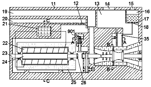
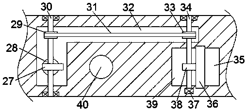
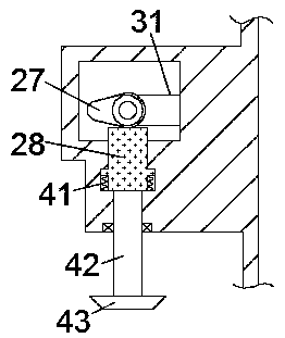
[0017] Combine below Figure 1-6 The present invention is described in detail, and for convenience of description, the orientations mentioned below are now stipulated as follows: figure 1 The up, down, left, right, front and back directions of the projection relationship itself are the same.

[0018] refer to Figure 1-6 , a gas turbine power generation equipment according to an embodiment of the present invention, including a gas turbine case 61 arranged in the generator body 11, a gas turbine chamber 62 is provided inside the gas turbine case 61, and an opening is provided on the left side of the gas turbine chamber 62 To the left air inlet 51, the left side of the air inlet 51 is communicated with an intake duct 19 capable of sending air outside the body into it, and a main shaft 56 is installed in the chamber 62 of the gas turbine, and the main shaft 56 is fixed The compressor impeller 52 that can increase the air flow rate is installed, the combustion chamber 58 is prov...


PUM


Abstract

The invention discloses gas turbine power generation equipment. The gas turbine power generation equipment comprises a gas turbine box arranged in a generator body, wherein a gas turbine cavity is arranged in the gas turbine box, and an air inlet with an opening facing left is formed in the left side of the gas turbine cavity. According to the gas turbine power generation equipment, the transmission connection between a main shaft and a generator shaft is realized through the meshing transmission between gears, so that a gas turbine and a generator are effectively connected; meanwhile, by utilizing the meshing between the gears and racks, the main shaft and the generator shaft are connected to drive the generator shaft to rotate to generate current while fuel oil enters into a combustion chamber of the gas turbine to combust to generate gas to drive the main shaft to rotate; and an air pump is started by part of electric energy generated through wires, so that air is circulated among components in a generator cavity, the purpose of cooling and temperature reduction is realized, and the condition that the mechanical performance of a machine is affected by working at high temperatureis effectively prevented.

Description

technical field [0001] The invention relates to the technical field of power generation, in particular to a gas turbine power generation equipment. Background technique [0002] During the combustion process of the gas turbine, the main shaft of the gas turbine needs to idle for a period of time while the fuel is burning to connect the generator shaft to the main shaft to ensure that there is enough energy to drive the generator shaft to rotate, which increases the fuel consumption required for power generation , and the generator shaft and the main shaft are connected by a coupling. If the coupling is damaged, the power generation process will be stopped and the power generation efficiency will be reduced. The gas turbine and generator will emit a lot of heat during operation and need to be stopped irregularly The operation achieves the purpose of heat dissipation, thereby reducing the power generation efficiency. Contents of the invention [0003] The object of the pres...

Claims


Application Information

Patent Timeline
Patent Type & Authority Applications(China)
IPC IPC(8): F02C7/36F02C7/18
CPCF02C7/18F02C7/36
Inventor 不公告发明人
Owner JINHUA LUORI NEW ENERGY TECH CO LTD
Why Eureka
Try Eureka